Rainbow Electronics MAX9597 User Manual
Page 25
MAX9597
Low-Power Audio/Video Interface
for Single SCART Connectors
______________________________________________________________________________________
25
The MAX9597 provides separate ground connections
for video and audio supplies. For best performance,
use separate ground planes for each of the ground
returns and connect all ground planes together at a sin-
gle point. Refer to the MAX9597 Evaluation Kit for a
proven circuit board layout example.
If the MAX9597 is mounted using flow soldering or
wave soldering, the ground via(s) for the exposed pad
should have a finished hole size of at least 14mil to
ensure adequate wicking of soldering onto the exposed
pad. If the MAX9597 is mounted using the solder mask
technique, the via requirement does not apply. In either
case, a good connection between the exposed pad
and ground is required to minimize noise from coupling
onto the outputs.
4
3
2
1
I
2
C INTERFACE
AND REGISTERS
MAX9597
VIDEO FILTERS
AUDIO
WITH DirectDrive
OUTPUTS
SLOW SWITCHING
FAST SWITCHING
CHARGE PUMP
V
12
V
AUD
V
ID
3.3V
3.3V
EP
GND
μC
VIDEO
ENCODER
STEREO
AUDIO
DAC
CVBS, Y/C
SINGLE OR
DIFFERENTIAL
STEREO AUDIO
STB CHIP
CVBS
Y
C
LEFT AUDIO
RIGHT AUDIO
I
2
C
N.C.
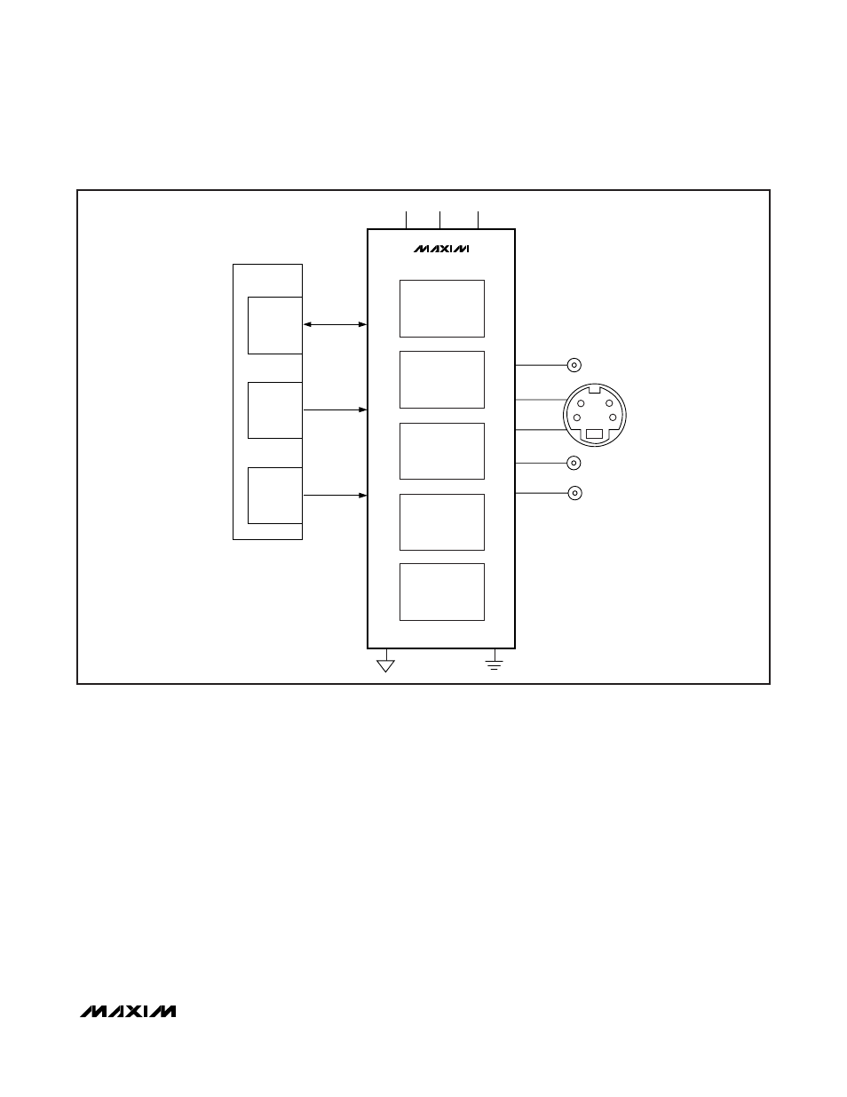
Figure 18. Set-Top Box with CVBS Output, S-Video Output, and Stereo Audio Outputs