Detailed description – Rainbow Electronics MAX9597 User Manual
Page 12
MAX9597
Low-Power Audio/Video Interface
for Single SCART Connectors
12
______________________________________________________________________________________
Detailed Description
The MAX9597 represents Maxim’s third generation of
SCART audio/video (A/V) switches. Under I
2
C control,
these devices route audio, video, and control informa-
tion between the set-top box decoder chip and a
SCART connector. The audio signals are left audio and
right audio. The video signals are composite video with
blanking and sync (CVBS) and component video (red,
green, blue). S-video (Y/C) can be transported across
the SCART interface if CVBS is reassigned to luma (Y)
and red is reassigned to chroma (C). Support for
S-video is optional. The slow-switch signal and the fast-
switch signal carry control information. The slow-switch
signal is a 12V, trilevel signal that indicates whether the
picture aspect ratio is 4:3, 16:9, or causes the television
to use an internal A/V source, such as an antenna. The
fast-switch signal indicates whether the television
should display CVBS or RGB signals.
CVBS, left audio, and right audio are full duplex. All the
other signals are half duplex. Therefore, one device on
the link must be designated as the transmitter, and the
other device must be designated as the receiver.
The low power consumption of the MAX9597 enables
the creation of lower power set-top boxes, televisions,
and DVD players. Unlike competing SCART ICs, the
audio and video circuits of the MAX9597 operate entirely
from 3.3V rather than from 5V and 12V. Only the slow-
switch circuit of the MAX9597 requires a 12V supply.
The MAX9597 features DirectDrive audio circuitry to
eliminate click-and-pop noise. With DirectDrive, the DC
bias of the audio line outputs is always at ground when
the MAX9597 is being powered up or powered down.
Conventional audio line output drivers that operate from
a single supply require series AC-coupling capacitors.
During power-up, the DC bias on the AC-coupling
capacitor moves from ground to a positive voltage, and
during power-down, the opposite occurs. The changing
DC bias usually causes an audible transient.
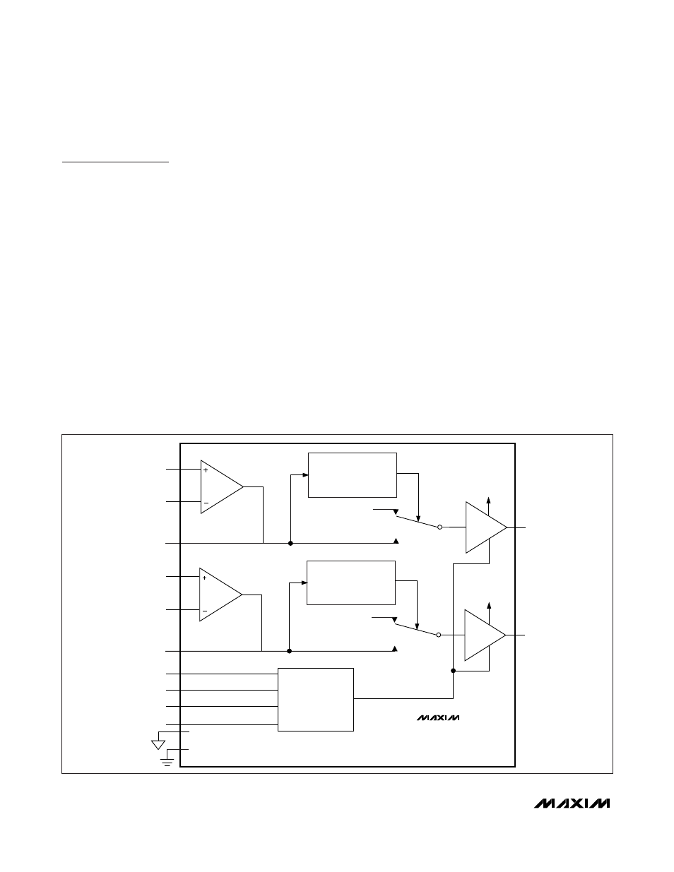
Audio Section
The audio circuit consists of a left and right audio path,
each with an independent operational amplifier fol-
lowed by a gain-of-4 amplifier. The encoder (stereo
audio DAC) is the input source, and the output goes to
the TV SCART connector. See Figure 1.
ZERO-CROSS
DETECTOR
ENC_INL+
TV_OUTL
CHARGE
PUMP
C1P
C1N
CPVSS
ENC_INL-
ENC_INLOUT
ZERO-CROSS
DETECTOR
ENC_INR+
EP
EP
TV_OUTR
ENC_INR-
ENC_INROUT
V
AUD
V
AUD
V
AUD
EP
A
V
= 4V/V
A
V
= 4V/V
INPUT
OP AMP
INPUT
OP AMP
MAX9597
Figure 1. MAX9597 Audio Section Functional Diagram