Applications information, Operating modes, Power consumption – Rainbow Electronics MAX9597 User Manual
Page 18
MAX9597
Low-Power Audio/Video Interface
for Single SCART Connectors
18
______________________________________________________________________________________
register address after each received data byte. This
autoincrement feature allows a master to write to
sequential register address locations within one contin-
uous frame. The master signals the end of transmission
by issuing a STOP condition.
Read Data Format
The master presets the address pointer by first sending
the MAX9597’s slave address with the R/W bit set to 0
followed by the register address after a START condi-
tion. The MAX9597 acknowledges receipt of its slave
address and the register address by pulling SDA low
during the ninth SCL clock pulse. A REPEATED START
condition is then sent followed by the slave address
with the R/W bit set to 1. The MAX9597 transmits the
contents of the specified register. Transmitted data is
valid on the rising edge of the master-generated serial
clock (SCL). The address pointer autoincrements after
each read data byte. This autoincrement feature allows
all registers to be read sequentially within one continu-
ous frame. A STOP condition can be issued after any
number of read data bytes. If a STOP condition is
issued followed by another read operation, the first
data byte to be read is from the register address loca-
tion set by the previous transaction and not 00h and
subsequent reads autoincrement the address pointer
until the next STOP condition. Attempting to read from
register addresses higher than 01h results in repeated
reads from a dummy register containing FFh data. The
master acknowledges receipt of each read byte during
the acknowledge clock pulse. The master must
acknowledge all correctly received bytes except the
last byte. The final byte must be followed by a not
acknowledge from the master and then a STOP condi-
tion. Figures 9 and 10 illustrate the frame format for
reading data from the MAX9597.
Applications Information
Operating Modes
The MAX9597 has two operating modes: full power
and shutdown. The operations can be set by writing to
bit 7 of register 10h. See Table 12.
In shudown mode, all circuitry is shut down except for
the I
2
C interface, which is designed with static CMOS
logic. If the I
2
C bus is quiet, the I
2
C interface draws
only leakage current.
Power Consumption
With a low 3.3V supply, the quiescent power consump-
tion and average power consumption of the MAX9597
is very low. Quiescent power consumption is defined
A
0
SLAVE ADDRESS
REGISTER ADDRESS
DATA BYTE
ACKNOWLEDGE FROM MAX9597
R/W
1 BYTE
AUTOINCREMENT INTERNAL
REGISTER ADDRESS POINTER
ACKNOWLEDGE FROM MAX9597
ACKNOWLEDGE FROM MAX9597
B1
B0
B3
B2
B5
B4
B7
B6
S
A
A
P
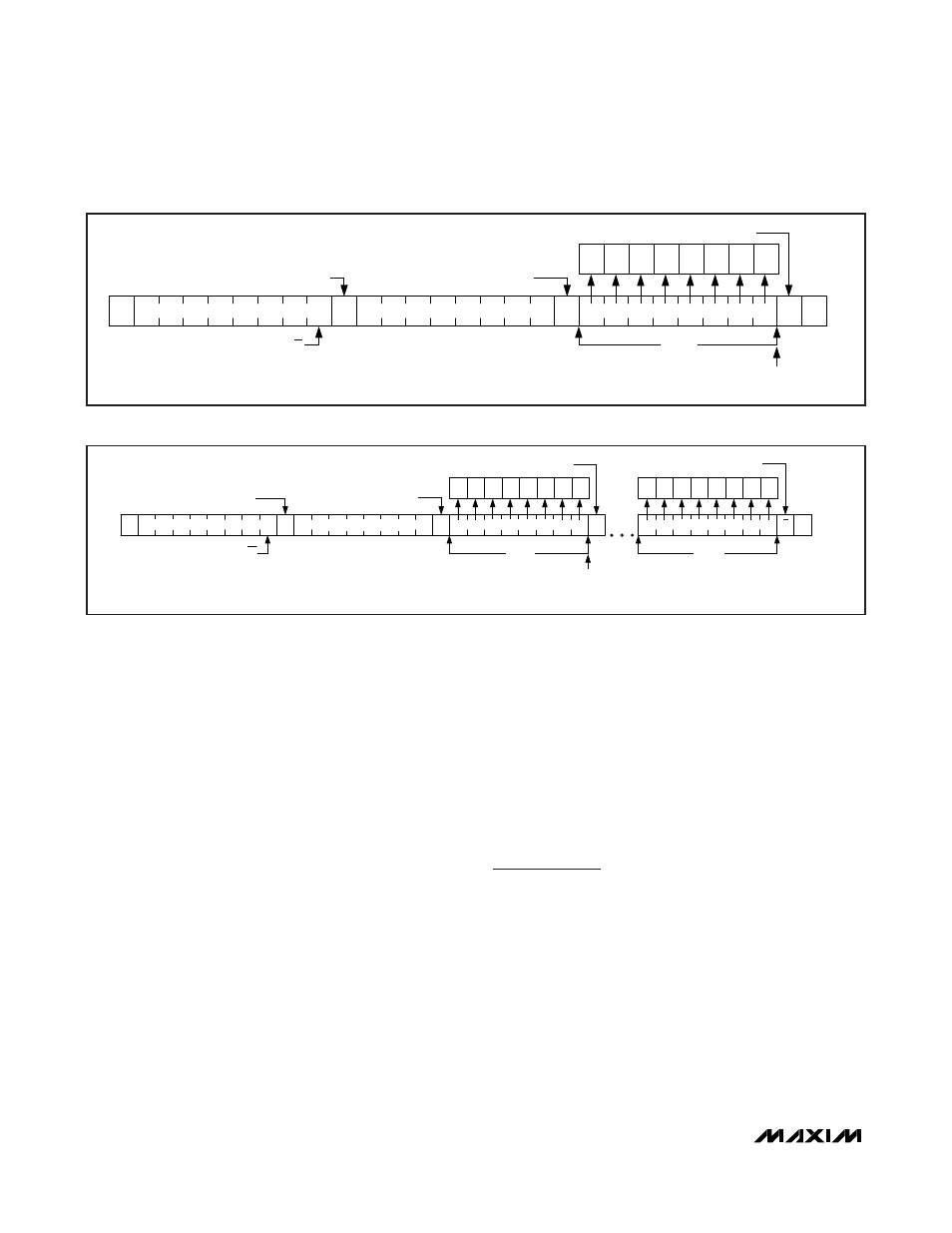
Figure 7. Writing a Byte of Data to the MAX9597
1 BYTE
AUTOINCREMENT INTERNAL
REGISTER ADDRESS POINTER
ACKNOWLEDGE FROM MAX9597
ACKNOWLEDGE FROM MAX9597
B1 B0
B3 B2
B5 B4
B7 B6
A
A
0
ACKNOWLEDGE FROM MAX9597
R/W
S
A
1 BYTE
ACKNOWLEDGE FROM MAX9597
B1 B0
B3 B2
B5 B4
B7 B6
P
A
SLAVE ADDRESS
REGISTER ADDRESS
DATA BYTE 1
DATA BYTE n
Figure 8. Writing n-Bytes of Data to the MAX9597