Rainbow Electronics MAX9597 User Manual
Page 23
MAX9597
Low-Power Audio/Video Interface
for Single SCART Connectors
______________________________________________________________________________________
23
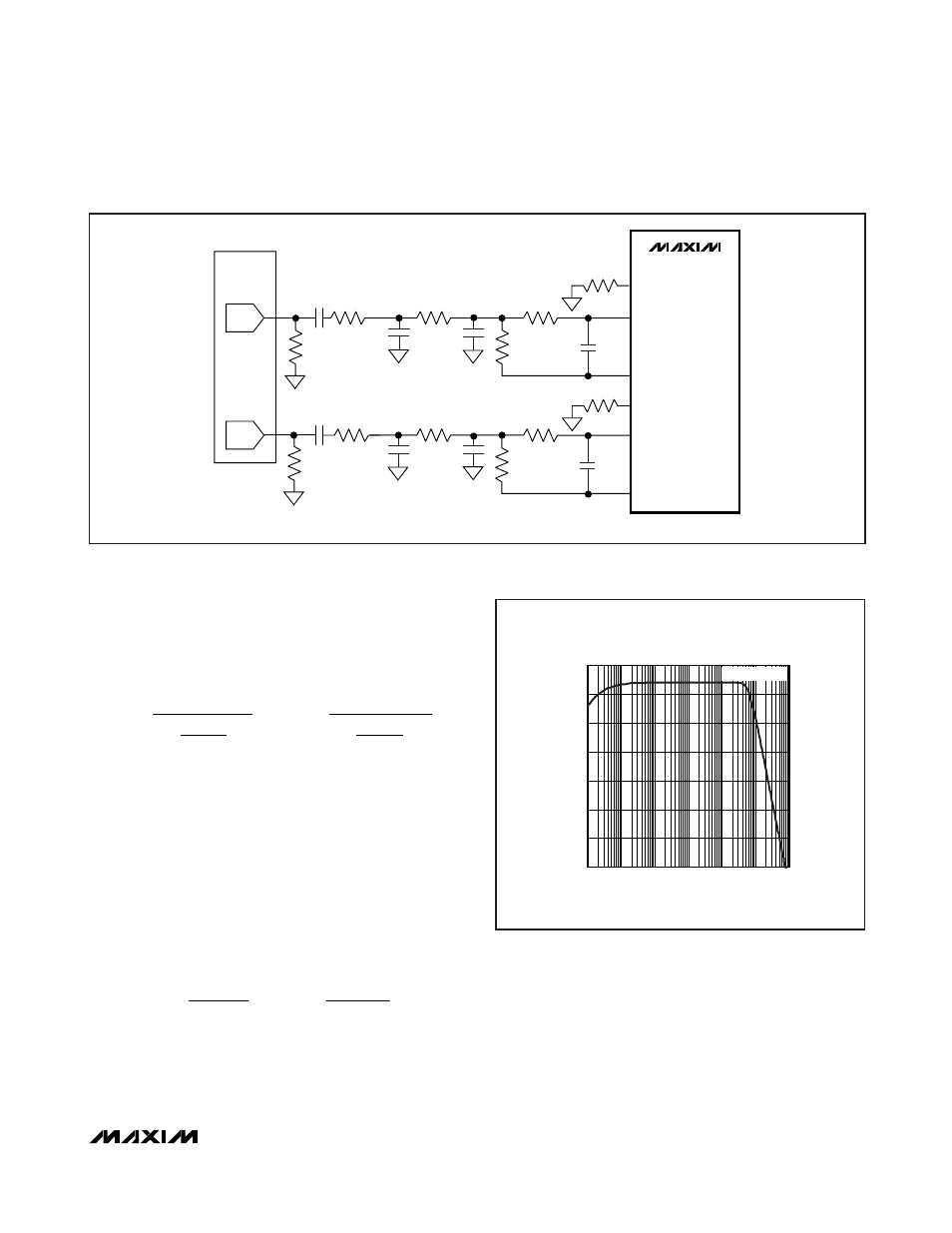
Keep the full-scale audio output of the preamplifiers to
0.5V
RMS
. Capacitors C1 and C2 create a one-pole,
lowpass filter to attenuate any high-frequency noise
coming from the stereo audio DAC. The frequency of
the lowpass pole is represented by this equation:
If the stereo audio DAC generates an analog, current
mode, and differential audio signal, the
Typical
Application Circuit
can be used to convert the signal to
single ended. The transresistance of the circuit is rep-
resented by this equation:
V
OUT
= I
DIFF
x R
F
Keep the full-scale audio output of the preamplifiers to
0.5V
RMS
. Capacitors C1 and C2 create a one-pole,
lowpass filter to attenuate any high-frequency noise
coming from the stereo audio DAC. The frequency of
the lowpass pole is represented by this equation:
f
R C
or f
R C
dB
F
dB
F
−
−
=
=
3
3
1
2
1
1
2
2
π
π
(
)
(
)
f
R
R
R
R
C
or f
R
dB
dB
−
−
=
Ч
+
⎛
⎝⎜
⎞
⎠⎟
=
Ч
3
3
1
2
1
2
1
2
1
1
2
1
π
π
R
R
R
R
C
2
1
2
2
+
⎛
⎝⎜
⎞
⎠⎟
MAX9597
10
μF
4.64k
Ω
ENC_INL+
ENC_INL-
ENC_INLOUT
ENC_INR+
10
μF
4.64k
Ω
ENC_INR-
ENC_INROUT
CS4334
DAC
3.57k
Ω
3.57k
Ω
2.40k
Ω
2.7nF
2.7nF
2.40k
Ω
LEFT
RIGHT
1.21k
Ω
1.21k
Ω
NOTE: ALL RESISTORS ARE 1%.
560pF
560pF
1.21k
Ω
1.21k
Ω
3.3nF
3.3nF
270k
Ω
270k
Ω
Figure 15. Lowpass Filter Configuration for the Cirrus CS4334
GAIN (dB)
-50
-40
-30
-20
-10
0
10
-60
FILTER RESPONSE vs. FREQUENCY
CS4334 APPLICATION CIRCUIT WITHOUT THE DAC
V
IN
= 0.25V
RMS
FREQUENCY (Hz)
100k
10k
1k
100
10
1
1M
Figure 16. Filter Response of CS4334 Filter Configuration