Electrical characteristics (continued) – Rainbow Electronics MAX17101 User Manual
Page 8
MAX17101
Dual Quick-PWM, Step-Down Controller
with Low-Power LDO, RTC Regulator
8
_______________________________________________________________________________________
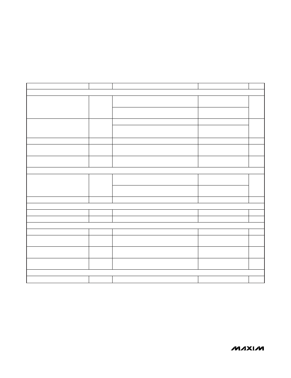
ELECTRICAL CHARACTERISTICS (continued)
(Circuit of Figure 1, no load on LDO, RTC, OUT1, OUT2, and REF, V
IN
= 12V, V
DD
= V
CC
= V
SECFB
= 5V, V
REFIN2
= 1.0V, BYP =
LDOSEL = GND, ONLDO = IN, ON1 = ON2 = V
CC
, T
A
= -40°C to +85°C, unless otherwise noted.) (Note 3)
PARAMETER
SYMBOL
CONDITIONS
MIN
TYP
MAX
UNITS
LINEAR REGULATOR (LDO)
V
IN
= 24V, LDOSEL = BYP = GND,
0 < I
LDO
< 100mA
4.85 5.15
LDO Output-Voltage Accuracy
V
LDO
V
IN
= 24V, LDOSEL = V
CC
, BYP = GND,
0 < I
LDO
< 100mA
3.20 3.40
V
LDOSEL low
0.25
LDOSEL Dual Mode
Voltage Level
LDOSEL high
V
CC
-
0.9V
V
LDO Short-Circuit Current
I
ILIM(LDO)
LDO = GND
260
mA
LDO Regulation Reduction/
Bypass Switchover Threshold
Falling edge of BYP
-12
-5
%
V
CC
Undervoltage-Lockout
Threshold
V
UVLO(VCC)
Falling edge of V
CC
,
PWM disabled below this threshold
3.8 4.3 V
3.3V ALWAYS-ON LINEAR REGULATOR (RTC)
ON1 = ON2 = GND, V
IN
= 6V to 24V,
0 < I
RTC
< 5mA
3.18 3.45
RTC Output-Voltage Accuracy
V
RTC
ON1 = ON2 = ONLDO = GND,
V
IN
= 6V to 24V, 0 < I
RTC
< 5mA
3.16 3.50
V
RTC Short-Circuit Current
I
ILIM(RTC)
RTC = GND
5
mA
REFERENCE (REF)
Reference Voltage
V
REF
V
CC
= 4.5V to 5.5V, I
REF
= 0
1.975
2.025
V
Reference Load-Regulation Error
V
REF
I
REF
= -20μA to +50μA
-10
+10
mV
OUT1 FAULT DETECTION
OUT1 Overvoltage Trip Threshold V
OVP(OUT1)
With respect to error-comparator threshold
10
20
%
OUT1 Undervoltage-Protection
Trip Threshold
V
UVP(OUT1)
With respect to error-comparator threshold
60
80
%
PGOOD1 Lower Trip Threshold
With respect to error-comparator threshold,
falling edge, hysteresis = 1%
-20 -10 %
PGOOD1 Output-Low Voltage
V
FB1
= 0.56V (PGOOD1 low impedance),
I
SINK
= 4mA
0.4
V
OUT2 FAULT DETECTION
OUT2 Overvoltage Trip Threshold V
OVP(OUT2)
With respect to error-comparator threshold
10
20
%