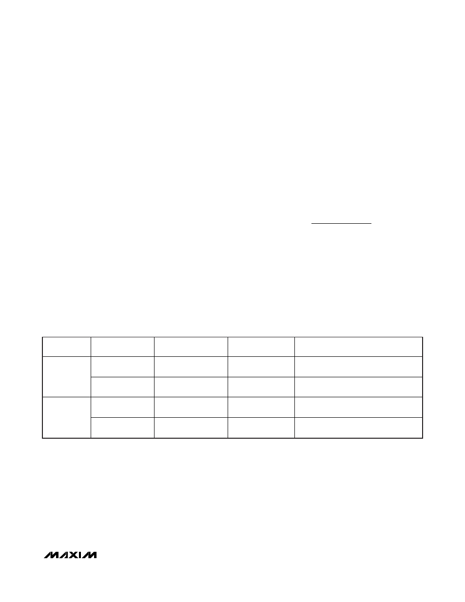
Table 3. approximate k-factor errors – Rainbow Electronics MAX17101 User Manual
Page 19
MAX17101
Dual Quick-PWM, Step-Down Controller
with Low-Power LDO, RTC Regulator
______________________________________________________________________________________
19
Free-Running Constant-On-Time PWM
Controller with Input Feed-Forward
The Quick-PWM control architecture is a pseudo-fixed-
frequency, constant on-time, current-mode regulator
with voltage feed-forward. This architecture relies on
the output filter capacitor’s ESR to act as a current-
sense resistor, so the feedback ripple voltage provides
the PWM ramp signal. The control algorithm is simple:
the high-side switch on-time is determined solely by a
one-shot whose pulse width is inversely proportional to
input voltage and directly proportional to output volt-
age. Another one-shot sets a minimum off-time (300ns
typ). The on-time one-shot is triggered if the error com-
parator is low, the low-side switch current is below the
valley current-limit threshold, and the minimum off-time
one-shot has timed out.
On-Time One-Shot
The heart of the PWM core is the one-shot that sets the
high-side switch on-time. This fast, low-jitter, adjustable
one-shot includes circuitry that varies the on-time in
response to battery and output voltage. The high-side
switch on-time is inversely proportional to the battery
voltage as sensed by the IN input, and proportional to
the output voltage:
On-Time = K (V
OUT
/V
IN
)
where K (switching period) is set by the trilevel TON
input (see the
Pin Description
section). High-frequency
(400kHz/500kHz) operation optimizes the application
for the smallest component size, trading off efficiency
due to higher switching losses. This might be accept-
able in ultra-portable devices where the load currents
are lower and the controller is powered from a lower
voltage supply. Low-frequency (200kHz/300kHz) oper-
ation offers the best overall efficiency at the expense of
component size and board space.
For continuous conduction operation, the actual switching
frequency can be estimated by:
where V
DROP1
is the sum of the parasitic voltage drops
in the inductor discharge path, including synchronous
rectifier, inductor, and PCB resistances; V
DROP2
is the
sum of the resistances in the charging path, including
the high-side switch, inductor, and PCB resistances;
and t
ON
is the on-time calculated by the MAX17101.
f
V
V
t
V
V
SW
OUT
DROP
ON
IN
DROP
=
+
+
1
2
(
)
SWITCHING
REGULATOR
TON SETTING
(kHz)
TYPICAL K-FACTOR
(μs)
K-FACTOR ERROR
(%)
COMMENTS
200
TON = V
CC
5.0
±10
Use for absolute best efficiency.
SMPS 1
400
TON = REF or GND
2.5 ±12.5
Useful in 3-cell systems for lighter loads
than the CPU core or where size is key.
300
TON = REF or V
CC
3.3 ±10
Considered mainstream by current
standards.
SMPS 2
500
TON = GND
2.0 ±12.5
Good operating point for compound buck
designs or desktop circuits.
Table 3. Approximate K-Factor Errors