Electrical characteristics (continued) – Rainbow Electronics MAX17101 User Manual
Page 4
MAX17101
Dual Quick-PWM, Step-Down Controller
with Low-Power LDO, RTC Regulator
4
_______________________________________________________________________________________
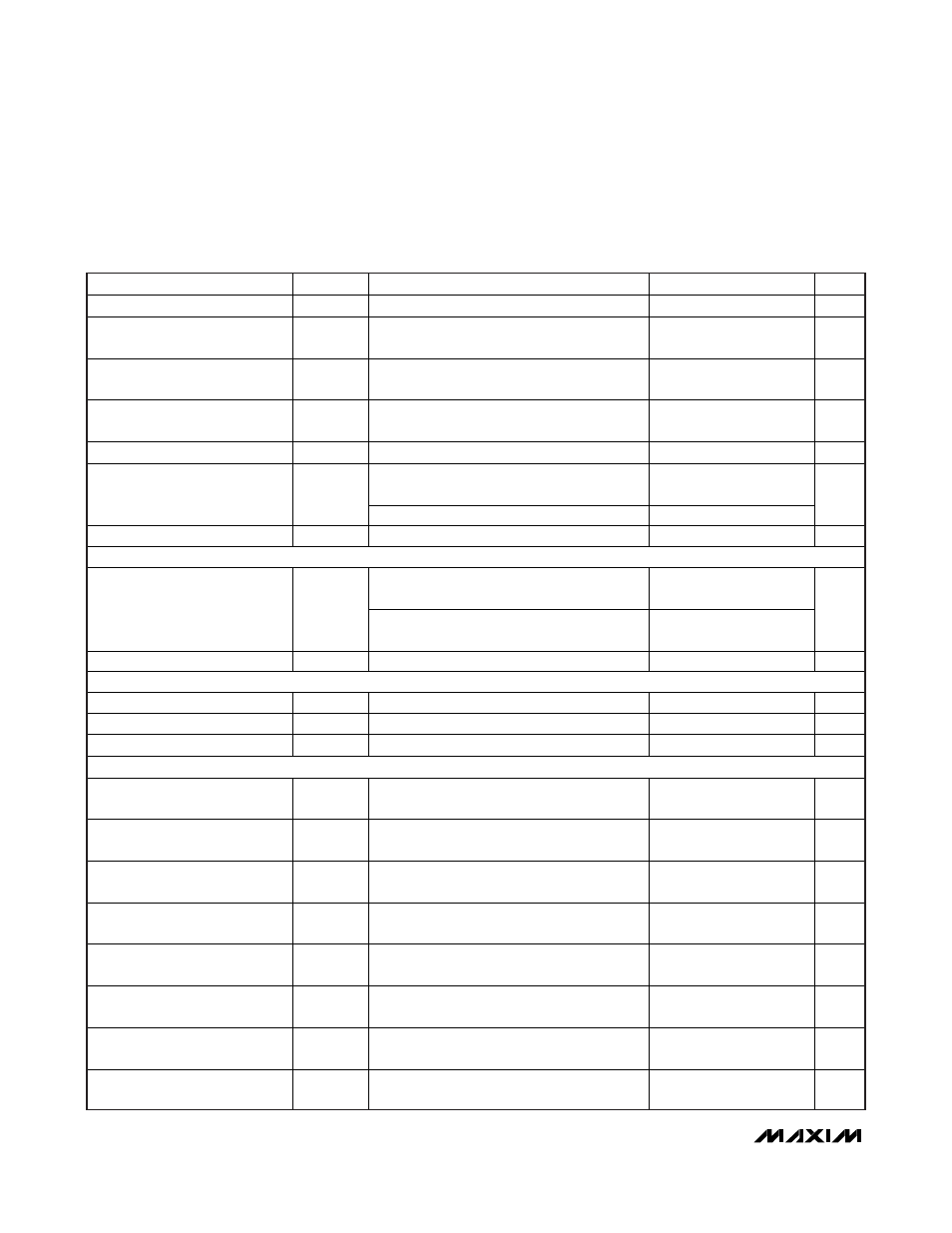
ELECTRICAL CHARACTERISTICS (continued)
(Circuit of Figure 1, no load on LDO, RTC, OUT1, OUT2, and REF, V
IN
= 12V, V
DD
= V
CC
= V
SECFB
= 5V, V
REFIN2
= 1.0V, BYP =
LDOSEL = GND, ONLDO = IN, ON1 = ON2 = V
CC
, T
A
= 0°C to +85°C, unless otherwise noted. Typical values are at T
A
= +25°C.)
PARAMETER
SYMBOL
CONDITIONS
MIN
TYP
MAX
UNITS
LDO Short-Circuit Current
I
ILIM(LDO)
LDO = GND
100
260
mA
LDO Regulation Reduction/
Bypass Switchover Threshold
With respect to the LDO voltage,
falling edge of BYP
-11.0 -8.5 -6.0 %
LDO Bypass Switchover
Threshold
With respect to the LDO voltage,
rising edge of BYP
-6.5 %
LDO Bypass Switchover
Startup Timeout
t
BYP
Rising edge of BYP to bypass gate pulled
low
500 μs
LDO Bypass Switch Resistance
LDO to BYP, V
BYP
= 5V (Note 4)
1.2
4.5
Falling edge of V
CC
,
PWM disabled below this threshold
3.8 4.0 4.3
V
CC
Undervoltage-Lockout
(UVLO) Threshold
V
UVLO(VCC)
Rising edge of V
CC
4.2
V
Thermal-Shutdown Threshold
T
SHDN
Hysteresis
=
10°C
+160 °C
3.3V ALWAYS-ON LINEAR REGULATOR (RTC)
ON1 = ON2 = GND, V
IN
= 6V to 24V,
0 < I
RTC
< 5mA
3.23 3.33 3.43
RTC Output-Voltage Accuracy
V
RTC
ON1 = ON2 = ONLDO = GND,
V
IN
= 6V to 24V, 0 < I
RTC
< 5mA
3.16 3.50
V
RTC Short-Circuit Current
I
ILIM(RTC)
RTC = GND
5
mA
REFERENCE (REF)
Reference Voltage
V
REF
V
CC
= 4.5V to 5.5V, I
REF
= 0
1.980
2.00
2.020
V
Reference Load Regulation
V
REF
I
REF
= -20μA to +50μA
-10
+10
mV
REF Lockout Voltage
V
REF(UVLO)
Rising edge, 350mV (typ) hysteresis
1.95
V
OUT1 FAULT DETECTION
OUT1 Overvoltage Trip
Threshold
V
OVP(OUT1)
With respect to error-comparator threshold
12
16
20
%
OUT1 Overvoltage
Fault-Propagation Delay
t
OVP
FB1 forced 50mV above trip threshold
10
μs
OUT1 Undervoltage Protection
Trip Threshold
V
UVP(OUT1)
With respect to error-comparator threshold
65
70
75
%
OUT1 Output-Undervoltage
Fault-Propagation Delay
t
UVP
10 μs
PGOOD1 Lower Trip Threshold
With respect to error-comparator threshold,
falling edge, hysteresis = 1%
-20 -16 -12 %
PGOOD1 Propagation Delay
t
PGOOD1
FB1 forced 50mV beyond PGOOD1 trip
threshold, falling edge
10 μs
PGOOD1 Output Low Voltage
V
FB1
= 0.56V (PGOOD1 low impedance),
I
SINK
= 4mA
0.3
V
PGOOD1 Leakage Current
I
PGOOD1
V
FB1
= 0.70V (PGOOD1 high impedance),
PGOOD1 forced to 5.5V
1
μA