Rainbow Electronics MAX17101 User Manual
Page 23
MAX17101
Dual Quick-PWM, Step-Down Controller
with Low-Power LDO, RTC Regulator
______________________________________________________________________________________
23
Adjustable/Fixed Output Voltages
Connect FB1 to GND for fixed 5V operation. Connect FB1
to V
CC
for fixed 1.5V operation. Connect FB1 to an exter-
nal resistive voltage-divider from OUT1 to analog ground
to adjust the output voltage between 0.7V and 5.5V.
During soft-shutdown, application circuits configured for
adjustable feedback briefly switch modes when FB1
drops below the 110mV dual-mode threshold.
Choose R
FBL
(resistance from FB1 to AGND) to be
approximately 49.9k
Ω and solve for R
FBH
(resistance
from OUT1 to FB1) using the following equation:
Connect REFIN2 to V
CC
for fixed 3.3V operation.
Connect REFIN2 to RTC (3.3V) for fixed 1.05V operation.
Connect REFIN2 to an external resistive voltage-divider
from REF to analog ground to adjust the output voltage
between 0.8V and 2V.
Choose R
REFINL
(resistance from REFIN2 to GND) to
be approximately 49.9k
Ω and solve for R
REFINH
(resis-
tance from REF to REFIN2) using the equation:
Power-Good Outputs (PGOOD)
and Fault Protection
PGOOD is the open-drain output that continuously
monitors the output voltage for undervoltage and over-
voltage conditions. PGOOD_ is actively held low in
shutdown (ON_ = GND), during soft-start or soft-shut-
down. Approximately 20μs (typ) after the soft-start
terminates, PGOOD_ becomes high impedance as long
as the feedback voltage exceeds 85% of the nominal
fixed-regulation voltage or within 150mV of the REFIN2
input voltage. PGOOD_ goes low if the feedback volt-
age drops 16% below the fixed target voltage, or if the
output voltage drops 150mV below the dynamic REFIN2
voltage, or if the SMPS controller is shut down. For a
logic-level PGOOD_ output voltage, connect an external
pullup resistor between PGOOD_ and V
DD
. A 100k
Ω
pullup resistor works well in most applications.
Overvoltage Protection (OVP)
When the output voltage rises 16% above the regula-
tion voltage, the controller immediately pulls the
respective PGOOD_ low, sets the overvoltage fault
latch, and immediately pulls the respective DL_ high—
clamping the output to GND. Toggle either ON1 or ON2
input, or cycle V
CC
power below its POR threshold to
clear the fault latch and restart the controller.
Undervoltage Protection (UVP)
When the output voltage drops 30% below the regula-
tion voltage, the controller immediately pulls the respec-
tive PGOOD_ low, sets the undervoltage fault latch, and
begins the shutdown sequence. After the output volt-
age drops below 0.1V, the synchronous rectifier turns
on, clamping the output to GND. Toggle either ON1 or
ON2 input, or cycle V
CC
power below its POR threshold
to clear the fault latch and restart the controller.
Thermal-Fault Protection (T
SHDN
)
The MAX17101 features a thermal-fault protection circuit.
When the junction temperature rises above +160°C, a
thermal sensor activates the fault latch, pulls PGOOD1
and PGOOD2 low, enables the 10
Ω discharge circuit,
and disables the controller—DH and DL pulled low.
Toggle ONLDO or cycle IN power to reactivate the con-
troller after the junction temperature cools by 15°C.
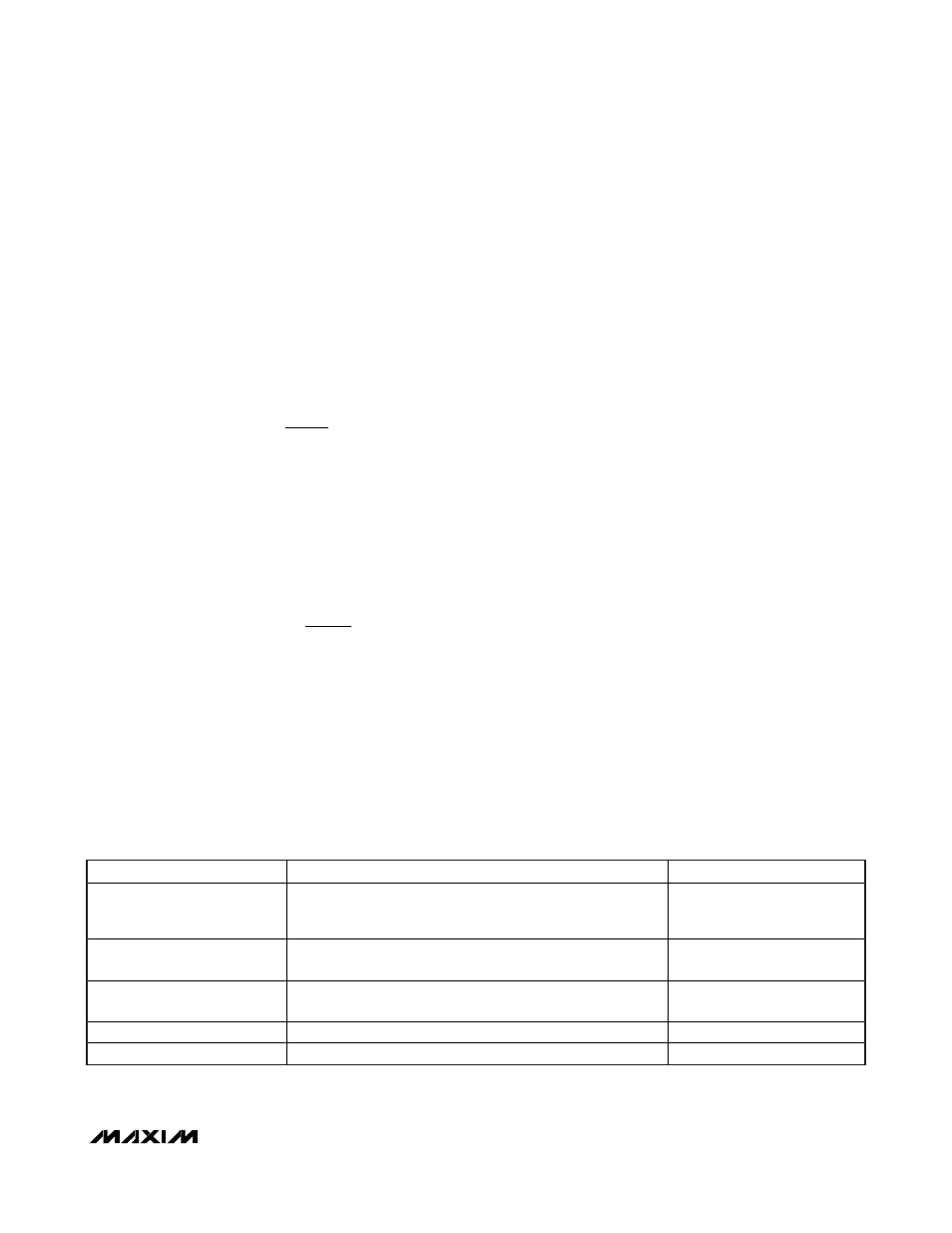
R
R
V
V
REFINH
REFINL
REF
OUT
=
−
⎛
⎝⎜
⎞
⎠⎟
2
1
R
R
V
V
FBH
FBL
OUT
=
−
⎛
⎝⎜
⎞
⎠⎟
1
0 7
1
.
MODE
CONTROLLER STATE
DRIVER STATE
Shutdown (ON_ = High to Low);
Output UVP (Latched)
Voltage soft-shutdown initiated. Internal error-amplifier target
slowly ramped down to GND and output actively discharged
(automatically enters forced-PWM mode).
DL driven high and DH pulled
low after soft-shutdown
completed (output < 0.1V).
Output OVP (Latched)
Controller shuts down and EA target internally slewed down.
Controller remains off until ON_ toggled or V
CC
power cycled.
DL immediately driven high,
DH pulled low.
V
CC
UVLO Falling-Edge
Thermal Fault (Latched)
SMPS controller disabled (assuming ON_ pulled high), 10
output discharge active.
DL and DH pulled low.
V
CC
UVLO Rising Edge
SMPS controller enabled (assuming ON_ pulled high).
DL driven high, DH pulled low.
V
CC
POR
SMPS inactive, 10
output discharge active.
DL driven high, DH pulled low.
Table 4. Fault Protection and Shutdown Operation Table