Applications information, Reset – Rainbow Electronics MAX4821 User Manual
Page 8
MAX4820/MAX4821
SET
/
RESET
Functions
The MAX4820/MAX4821 feature set and reset inputs that
allow the user to simultaneously turn all outputs on or off
using a single control line. Drive SET low to set all latch-
es and registers to 1 and turn all outputs on. SET over-
rides all serial/parallel control inputs. Drive RESET low to
clear all latches and registers and turn all outputs off.
RESET overrides all other inputs, including SET.
Applications Information
Daisy Chaining
The MAX4820 features a digital output, DOUT, that pro-
vides a simple way to daisy chain multiple devices. This
feature allows the user to drive large banks of relays
using only a single serial interface. To daisy chain multi-
ple devices, connect all CS pins together, and connect
the DOUT of one device to the DIN of another device
(see Figure 3). During operation, a stream of serial data
is shifted through all the MAX4820s in series. When CS
goes high, all outputs update simultaneously.
The MAX4820 can also be used in a slave configuration
that allows the user to address individual devices.
Connect all the DIN pins together, and use the CS input
to address one device at a time. Drive CS low to select
a slave and input the data into the shift register. Drive
CS high to latch the data and turn on the appropriate
outputs. Typically, in this configuration only one slave is
addressed at a time.
+3.3V/+5V, 8-Channel, Cascadable Relay Drivers
with Serial/Parallel Interface
8
_______________________________________________________________________________________
CS
A_
LVL
V
OUT
t
AS
t
AH
t
LS
t
LH
t
ON
,
t
OFF
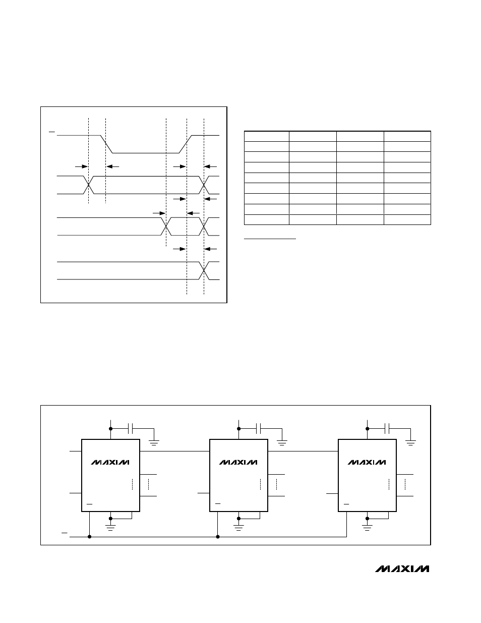
Figure 2. Parallel Interface Timing Diagram (MAX4821 only)
MAX4820
DIN
DIN
SCLK
SCLK
CS
SCLK
DOUT
OUT8
PGND
CS
V
CC
V
CC
0.1
µF
GND
OUT1
MAX4820
DIN
SCLK
DOUT
OUT8
PGND
CS
V
CC
V
CC
0.1
µF
GND
OUT1
MAX4820
DIN
SCLK
DOUT
OUT8
PGND
CS
V
CC
V
CC
0.1
µF
GND
OUT1
SCLK
Figure 3. Daisy-Chain Configuration
Table 2. Parallel Interface Address Map
(MAX4821 Only)
A2
A1
A0
OUTPUT
Low
Low
Low
OUT1
Low
Low
High
OUT2
Low
High
Low
OUT3
Low
High
High
OUT4
High
Low
Low
OUT5
High
Low
High
OUT6
High
High
Low
OUT7
High
High
High
OUT8