Typical operating characteristics (continued), Pin description – Rainbow Electronics MAX4821 User Manual
Page 5
MAX4820/MAX4821
3.3V/+5V, 8-Channel, Cascadable Relay Drivers
with Serial/Parallel Interface
_______________________________________________________________________________________
5
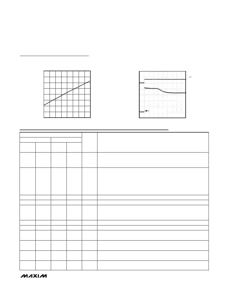
INPUT LOGIC THRESHOLD
vs. SUPPLY VOLTAGE
MAX4820 toc10
SUPPLY VOLTAGE (V)
INPUT LOGIC THRESHOLD (V)
5.1
4.7
2.7
3.1
3.5
3.9
4.3
0.75
1.00
1.25
1.50
1.75
2.00
2.25
2.50
0.50
2.3
5.5
PIN
MAX4820
MAX4821
THIN
QFN
TSSOP
THIN
QFN
TSSOP
NAME
FUNCTION
1
3
1
3
RESET
Reset Input. Drive RESET low to clear all latches and registers (all outputs
are turned off). RESET overrides all other inputs. If RESET and SET are pulled
low at the same time, then RESET takes precedence.
2
4
2
4
CS
Chip-Select Input.
MAX4820: Drive CS low to select the device. When CS is low, data at DIN is
clocked into the 8-bit shift register on SCLK’s rising edge. Drive CS from low
to high to latch the data to the registers and activate the appropriate relays.
MAX4821: Drive CS low to select the device and set level on LVL. Drive CS
from low to high to latch the address and level data to the output.
3
5
—
—
DIN
Serial Data Input
4
6
—
—
SCLK
Serial Clock Input
5
7
—
—
DOUT
Serial Data Output. DOUT is the output of the 8-bit shift register. This output
can be used to daisy chain multiple MAX4820s. The data at DOUT appears
synchronous to SCLK’s falling edge.
6
8
—
—
N.C.
No Connection
7
9
7
9
GND
Ground
8
10
8
10
OUT8
Open-Drain Output 8. Connect OUT8 to the low side of a relay coil. This
output is pulled to PGND when activated, but otherwise is high impedance.
9
11
9
11
OUT7
Open-Drain Output 7. Connect OUT7 to the low side of a relay coil. This
output is pulled to PGND when activated, but otherwise is high impedance.
10, 16
12, 18
10, 16
12, 18
PGND
Power Ground. PGND is a return for the output sinks. Connect PGND pins
together and to GND.
11
13
11
13
OUT6
Open-Drain Output 6. Connect OUT6 to the low side of a relay coil. This
output is pulled to PGND when activated, but otherwise is high impedance.
Typical Operating Characteristics (continued)
(V
COM
= V
CC
, T
A
= -40°C to +85°C, unless otherwise noted. Typical values are at T
A
= +25°C.)
BACK EMF CLAMPING
WITH STANDARD 3V RELAY
MAX4820 toc11
200
µs/div
V
CS
5V/div
0
0
OUT_
1V/div
OUT_ TURNS OFF
V
CC
= 3.3V
Pin Description