Pin description (continued), Detailed description – Rainbow Electronics MAX16834 User Manual
Page 7
MAX16834
High-Power LED Driver with Integrated High-Side LED
Current Sense and PWM Dimming MOSFET Driver
_______________________________________________________________________________________
7
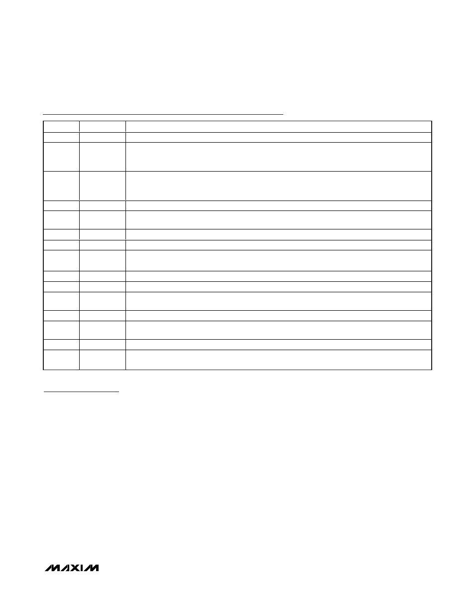
Pin Description (continued)
PIN
NAME
FUNCTION
7
FLT
Active-Low, Open-Drain Fault Indicator Output. See the Fault Indicator (FLT) section.
8
RT/SYNC
Resistor-Programmable Switching Frequency Setting/Sync Control Input. Connect a resistor from
RT/SYNC to SGND to set the switching frequency. Drive RT/SYNC to synchronize the switching
frequency with an external clock.
9
UVEN
Undervoltage-Lockout (UVLO) Threshold/Enable Input. UVEN is a dual-function adjustable UVLO
threshold input with an enable feature. Connect UVEN to V
IN
through a resistive voltage-divider to
program the UVLO threshold. Observe the absolute maximum value for this pin.
10
PWMDIM
PWM Dimming Input. Connect to an external PWM signal for dimming operation.
11
CS
Current-Sense Amplifier Positive Input. Connect a resistor from CS to PGND to set the inductor peak
current limit.
12
PGND
Power Ground
13
NDRV
External n-Channel Gate-Driver Output
14
V
CC
7V Low-Dropout Voltage Regulator. Bypass to PGND with at least a 1µF low-ESR ceramic capacitor.
V
CC
provides power to the n-channel gate driver (NDRV).
15
IN
Positive Power-Supply Input. Bypass to PGND with at least a 0.1µF ceramic capacitor.
16
HV
High-Side Positive Supply Input Referred to LV. HV provides power to high-side linear regulator CLV.
17
CLV
5V High-Side Regulator Output. CLV provides power to the dimming MOSFET driver. Connect a 0.1µF
to 1µF ceramic capacitor from CLV to LV for stable operation.
18
DIMOUT
External Dimming MOSFET Gate Driver. DIMOUT is capable of sinking/sourcing 50mA.
19
LV
High-Side Reference Voltage Input. Connect to SGND for boost configuration. Connect to IN for buck-
boost configuration.
20
SENSE+
LED Current-Sense Positive Input
—
EP
Exposed Pad. Connect EP to a large-area contiguous copper ground plane for effective power
dissipation. Do not use as the main IC ground connection. EP must be connected to SGND.
Detailed Description
The MAX16834 is a current-mode, high-brightness LED
(HB LED) driver designed to control a single-string LED
current regulator with two external n-channel MOSFETs.
The MAX16834 integrates all the building blocks nec-
essary to implement a fixed-frequency HB LED driver
with wide-range dimming control. The MAX16834
allows implementation of different converter topologies
such as SEPIC, boost, buck-boost, or high-side buck
current regulator.
The MAX16834 features a constant-frequency, peak-cur-
rent-mode control with programmable slope compensa-
tion to control the duty cycle of the PWM controller. A
dimming driver offers a wide-range dimming control for
the external n-channel MOSFET in series with the LED
string. In addition to PWM dimming, the MAX16834
allows for analog dimming of LED current.
The MAX16834 switching frequency (100kHz to 1MHz)
is adjustable using a single resistor from RT/SYNC. The
MAX16834 disables the internal oscillator and synchro-
nizes if an external clock is applied to RT/SYNC. The
switching MOSFET driver sinks and sources up to 3A,
making it suitable for high-power MOSFETs driving in
HB LED applications, and the dimming control allows
for wide PWM dimming at frequencies up to 20kHz.
The MAX16834 is suitable for boost and buck-boost
LED drivers (Figures 2 and 3).
The MAX16834 operates over a wide 4.75V to 28V sup-
ply range. Additional features include external
enable/disable input, an on-chip oscillator, fault indica-
tor output (FLT) for LED open/short or overtemperature
conditions, and an overvoltage protection circuit for
true differential overvoltage protection (Figure 1).
The MAX16834 is also suitable for DC-DC converter
applications such as boost or buck-boost (Figures 6
and 7). Other applications include boost LED drivers
with automotive load dump protection (Figure 4) and
high-side buck LED drivers (Figure 5).