Rainbow Electronics MAX16834 User Manual
Page 11
MAX16834
High-Power LED Driver with Integrated High-Side LED
Current Sense and PWM Dimming MOSFET Driver
______________________________________________________________________________________
11
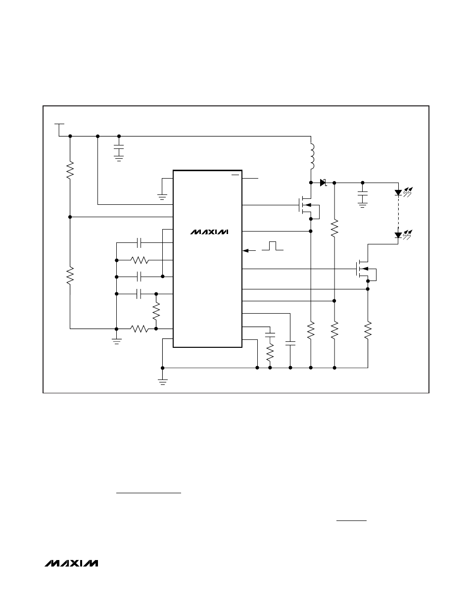
Boost Configuration
In the boost converter (Figure 2), the average inductor
current varies with the line voltage. The maximum aver-
age current occurs at the lowest line voltage. For the
boost converter, the average inductor current is equal
to the input current.
Calculate maximum duty cycle using the below equation.
where V
LED
is the forward voltage of the LED string in
volts, V
D
is the forward drop of the rectifier diode D1 in
volts (approximately 0.6V), V
INMIN
is the minimum input
supply voltage in volts, and V
FET
is the average drain to
source voltage of the MOSFET Q1 in volts when it is on.
Use an approximate value of 0.2V initially to calculate
D
MAX
. A more accurate value of the maximum duty
cycle can be calculated once the power MOSFET is
selected based on the maximum inductor current.
Use the following equations to calculate the maximum
average inductor current IL
AVG
, peak-to-peak inductor
current ripple
∆I
L
, and the peak inductor current IL
P
in
amperes:
IL
I
D
AVG
LED
MAX
=
−
1
D
V
V
V
V
V
V
MAX
LED
D
INMIN
LED
D
FET
=
+
−
+
−
V
IN
LV
NDRV
Q1
ON
OFF
CS
C1
PWMDIM
SGND
D1
R10
R8
MAX16834
FLT
DIMOUT
SENSE+
OVP+
CLV
COMP
PGND
C3
UVEN
HV
SC
RT/SYNC
C2
IN
L1
V
CC
C5
REF
C4
R3
REFI
R5
R6
R2
R1
R9
R4
C7
R7
Q2
C6
LED+
LEDs
LED-
Figure 2. Boost LED Driver