Electrical characteristics (continued) – Rainbow Electronics MAX16834 User Manual
Page 4
MAX16834
High-Power LED Driver with Integrated High-Side LED
Current Sense and PWM Dimming MOSFET Driver
4
_______________________________________________________________________________________
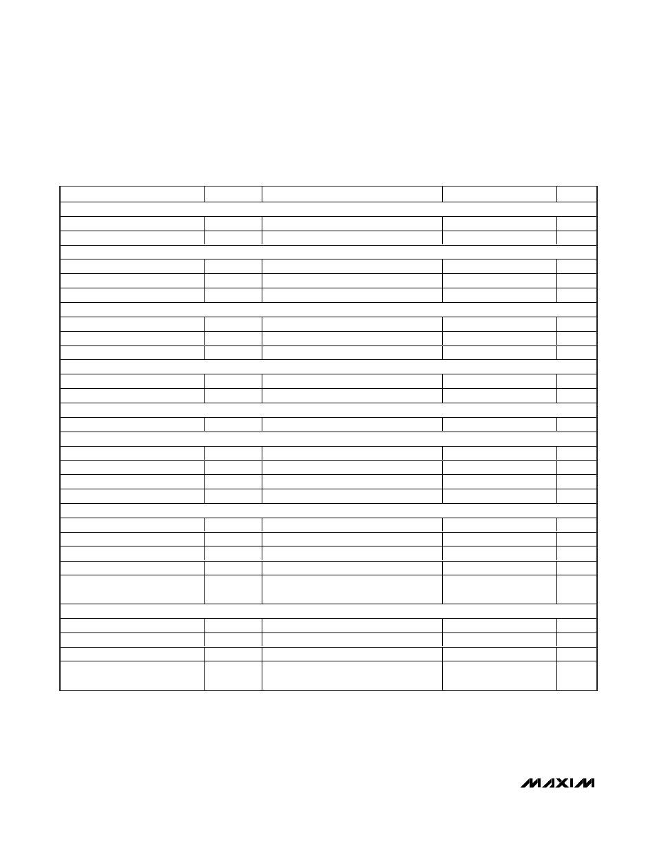
ELECTRICAL CHARACTERISTICS (continued)
(V
IN
= V
HV
= 12V, V
UVEN
= 5V, V
LV
= V
PWMDIM
= SGND, C
VCC
= 4.7µF, C
LCV
= 100nF, C
REF
= 100nF, R
SENSE+
= 0.1
Ω,
R
RT
= 10k
Ω, T
A
= T
J
= -40°C to +125°C, unless otherwise noted. Typical values are at T
A
= +25°C.)
PARAMETER
SYMBOL
CONDITIONS
MIN
TYP
MAX
UNITS
CURRENT PEAK LIMIT COMPARATOR
Trip Threshold Voltage
0.25
0.3
0.35
V
Propagation Delay
50mV overdrive with respect to NDRV
40
ns
OVERVOLTAGE PROTECTION INPUT (OVP+)
OVP+ On Threshold Voltage
V
OVP_ON
1.375
1.435
1.495
V
OVP+ Hysteresis
200
mV
OVP+ Input Leakage Current
(V
OVP
- V
LV
) = 1.235V
-1
+1
µA
HIGH-SIDE LED SHORT COMPARATOR
Off Threshold
V
CLV
- V
LV
4.0
4.3
4.6
V
On Threshold
V
CLV
- V
LV
4.1
4.4
4.7
V
Error Reject Blankout
f
OSC
= 500kHz
256
µs
LOW-SIDE LED SHORT COMPARATOR
Off Threshold
0.27
0.30
0.33
V
Error Reject Blankout
5
µs
HICCUP TIMER
Hiccup Time
f
OSC
= 500kHz
8.2
ms
GATE-DRIVER OUTPUT (NDRV)
NDRV Peak Pullup Current
V
CC
= 7V
3
A
NDRV Peak Pulldown Current
V
CC
= 7V
3
A
p-Channel MOSFET R
DSON
(V
CC
- V
NDRV
) = 0.1V
1.2
1.9
Ω
n-Channel MOSFET R
DSON
V
NDRV
= 0.1V
0.9
1.7
Ω
DIMOUT
DIMOUT Peak Pullup Current
(V
CLV
- V
LV
) = 5V
25
50
mA
DIMOUT Peak Pulldown Current
(V
CLV
- V
LV
) = 5V
25
50
mA
p-Channel MOSFET R
DSON
(V
CLV
- V
DIMOUT
) = 0.1V
31
Ω
n-Channel MOSFET R
DSON
(V
DIMOUT
- V
LV
) = 0.1V
25
Ω
PWMDIM to DIMOUT
Propagation Delay
200
ns
FAULT FLAG (
FLT)
FLT Pulldown Current
V
FLT
= 0.2V
2
5
10
mA
FLT Leakage Current
V
FLT
= 1.0V
I1I
µA
Thermal Warning On Threshold
+140
°C
Thermal Warning Threshold
Hysteresis
20
°C
Note 2: Dropout voltage is defined as V
IN
- V
CC
, when V
CC
is 100mV below the value of V
CC
for V
IN
= 9.5V.
Note 3: Dropout is defined as V
HV
- V
CLV
, when V
CLV
is 100mV below the value of V
CLV
for V
HV
= 8V.
Note 4: Not production tested. Guaranteed by design.