Electrical characteristics (continued) – Rainbow Electronics MAX9768 User Manual
Page 3
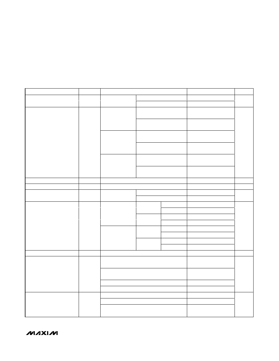
MAX9768
10W Mono Class D Speaker
Amplifier with Volume Control
_______________________________________________________________________________________
3
PARAMETER
SYMBOL
CONDITIONS
MIN
TYP
MAX
UNITS
Filterless modulation
87
Efficiency (Note 2)
η
P
OUT
= 8W, f
IN
=
1kHz, R
L
= 8
Ω
Classic PWM modulation
85
%
R
L
= 8
Ω, THD+N = 1%,
filterless modulation
1.3
PV
DD
= 5V
R
L
= 8
Ω, THD+N = 10%,
filterless modulation
1.7
R
L
= 8
Ω, THD+N = 10%,
classic PWM modulation
9
PV
DD
= 12V
R
L
= 8
Ω, THD+N = 10%,
filterless modulation
9
R
L
= 8
Ω, THD+N = 10%,
classic PWM modulation
10
Output Power (Note 2)
P
OUT
PV
DD
= 14V
R
L
= 8
Ω, THD+N = 10%,
filterless modulation
10
W
Soft Output Current Limit
I
LIM
1.75
2
A
Hard Output Current Limit
I
SC
2.5
A
Filterless modulation
0.09
Total Harmonic Distortion
Plus Noise (Note 2)
THD+N
f = 1kHz, R
L
= 8
Ω,
P
OUT
= 5W
Classic PWM modulation
0.08
%
FFM
94
Unweighted
SSM
93
FFM
97
0dB = 8W, R
L
=
8
Ω, BW = 22Hz to
22kHz, filterless
modulation mode
A-weighted
SSM
97
FFM
93
Unweighted
SSM
89
FFM
97
Signal-to-Noise Ratio
(Note 2)
SNR
0dB = 8W, R
L
=
8
Ω, BW = 22Hz to
22kHz, classic
PWM modulation
A-weighted
SSM
91
dB
MUTE Attenuation (Note 3)
0dB = 8W, f = 1kHz
115
dB
V
DD
= 2.7V to 3.6V, filterless modulation,
T
A
= +25°C
52
68
PV
DD
= 4.5V to 14V, filterless modulation,
T
A
= +25°C
67
84
f = 1kHz, V
RIPPLE
= 200mV
P-P
on PV
DD
77
Power-Supply Rejection
Ratio
PSRR
f = 1kHz, V
RIPPLE
= 100mV
P-P
on V
DD
60
dB
SYNC = GND
1060
1200
1320
SYNC = unconnected
1296
1440
1584
Oscillator Frequency
f
OCS
SYNC = V
DD
(spread-spectrum modulation
mode)
1200
±30
kHz
ELECTRICAL CHARACTERISTICS (continued)
(PV
DD
= 12V, V
DD
= 3.3V, GND = PGND = 0V, V
SHDN
= V
DD
, V
MUTE
= 0V; Max volume setting; speaker load resistor connected
between OUT+ and OUT-, R
L
=
∞, unless otherwise noted. C
BIAS
= 2.2µF, C1 = C2 = 0.1µF, C
IN
= 0.47µF, R
IN
= 20k
Ω, R
F
= 30kΩ,
SSM mode. Filterless modulation mode (see the
Functional Diagram/Typical Application Circuit). T
A
= T
MIN
to T
MAX
, unless otherwise
noted. Typical values are at T
A
= +25°C.) (Note 1)