Table 3. slave address block, Table 4. slave address – Rainbow Electronics MAX9768 User Manual
Page 17
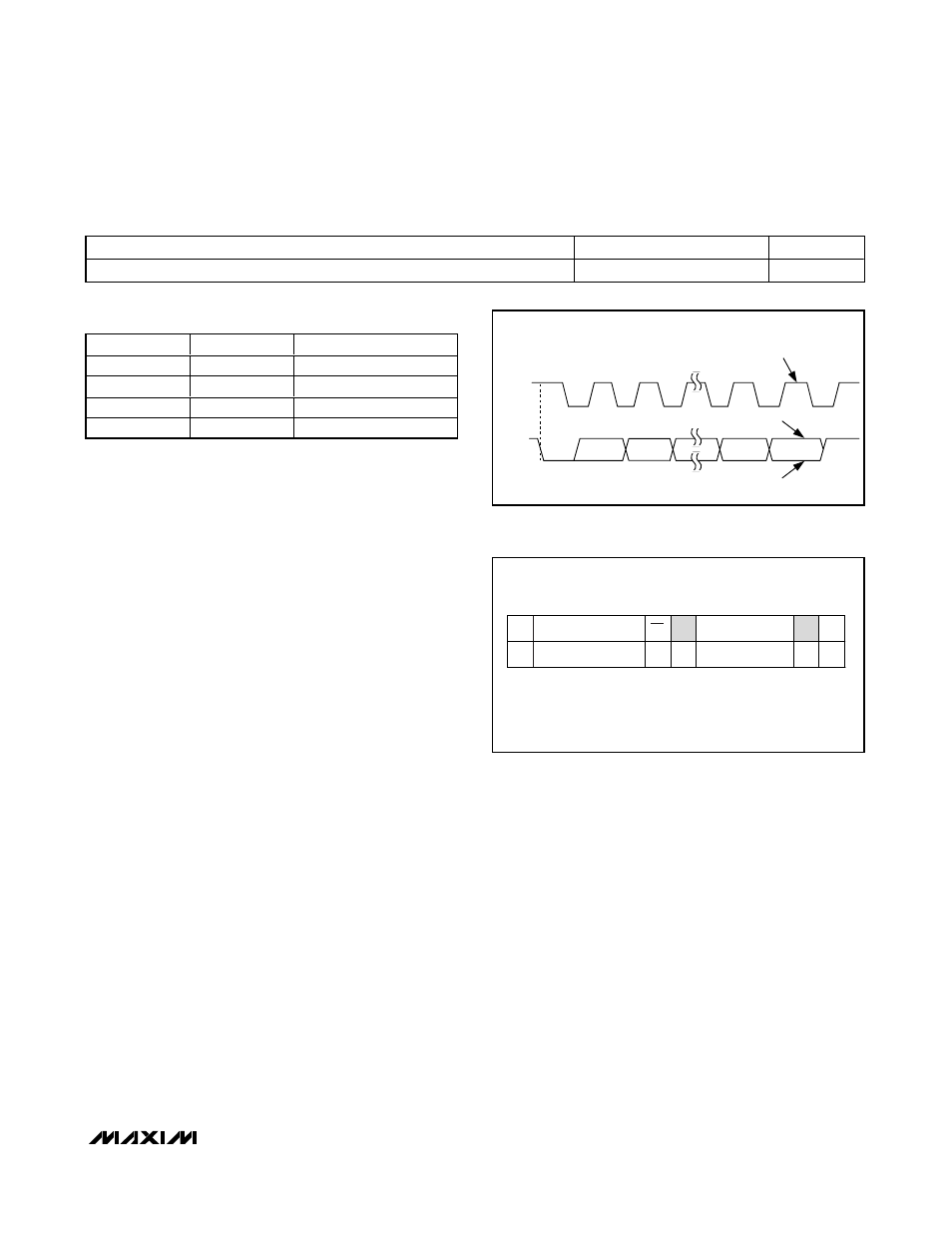
Write Data Format
A write to the MAX9768 includes transmission of a
START condition, the slave address with the R/
W bit set
to 0 (see Table 3), one byte of data to the command
register, and a STOP condition. Figure 6 illustrates the
proper format for one frame.
Volume Control
The command register is used to control the volume
level of the speaker amplifier. The two MSBs (D7 and
D6) should be set to 00 to choose the speaker register.
V5–V0 is the volume control data that will be written into
the addresses register to set the volume level (see
Tables 5 and 6).
For a write byte operation, the master sends a single byte
to the slave device (MAX9768). This is done as follows:
1) The master sends a start condition.
2) The master sends the 7-bit slave ID plus a write bit
(low).
3) The addressed slave asserts an ACK on the data
line.
4) The master sends 8 data bits.
5) The active slave asserts an ACK (or NACK) on the
data line.
6) The master generates a stop condition.
MAX9768
10W Mono Class D Speaker
Amplifier with Volume Control
______________________________________________________________________________________
17
Table 3. Slave Address Block
SA7 (MSB)
SA6
SA5
SA4
SA3
SA2
SA1
SA0 (LSB)
1
0
0
1
0
ADDR2
ADDR1
R/
W
Table 4. Slave Address
ADDR2
ADDR1
SLAVE ADDRESS
0
0
Disabled
0
1
1001001_
1
0
1001010_
1
1
1001011_
1
SCL
START
CONDITION
SDA
2
8
9
CLOCK PULSE FOR
ACKNOWLEDGMENT
ACKNOWLEDGE
NOT ACKNOWLEDGE
Figure 5. Acknowledge
S
SLAVE ADDRESS
7 bits
WRITE BYTE FORMAT
WR
ACK
DATA
8 bits
ACK
P
DATA BYTE: GIVES A COMMAND.
SLAVE ADDRESS:
EQUIVALENT TO CHIP-
SELECT LINE OF A 3-
WIRE INTERFACE.
0
Figure 6. Write Data Format Example