Table 8. suggested values for lc filter – Rainbow Electronics MAX9768 User Manual
Page 21
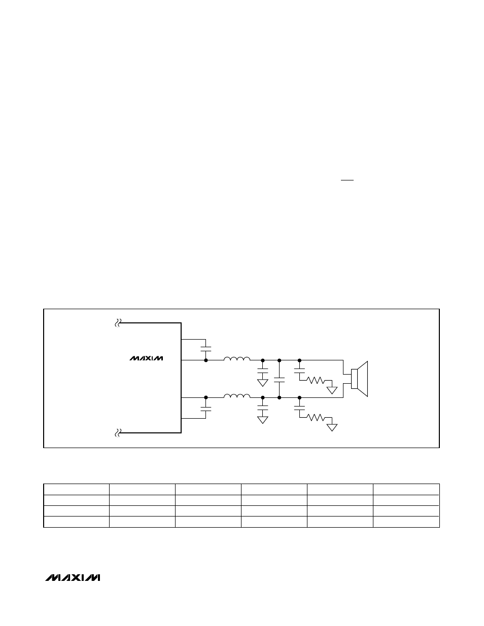
Inductor-Based Output Filters
Some applications will use the MAX9768 with a full
inductor-/capacitor-based (LC) output filter. This is
common for longer speaker lead lengths, and to gain
increased margin to EMC limits. Select the PWM output
mode and use fixed-frequency modulation mode for
best audio performance. See Figure 8 for the correct
connections of these components.
The component selection is based on the load imped-
ance of the speaker. Table 8 lists suggested values for
a variety of load impedances.
Inductors L3 and L4, and capacitor C15 form the pri-
mary output filter. In addition to these primary filter
components, other components in the filter improve its
functionality. Capacitors C13 and C14, plus resistors
R6 and R7, form a Zobel at the output. A Zobel corrects
the output loading to compensate for the rising imped-
ance of the loudspeaker. Without a Zobel, the filter will
have a peak in its response near the cutoff frequency.
Capacitors C11 and C12 provide additional high-fre-
quency bypass to reduce radiated emissions.
Adjustable Gain
Gain-Setting Resistors
External feedback resistors set the gain of the
MAX9768. The output stage has an internal 20dB gain
in addition to the externally set gain. Set the maximum
gain by using resistors R
F
and R
IN
(Figure 9
)
as follows:
Choose R
F
between 10kΩ and 50kΩ. Please note that
the actual gain of the amplifier is dependent on the vol-
ume level setting. For example, with the volume control
set to +9.5dB, the amplifier gain would be 9.5dB +
20dB, assuming R
F
= R
IN
.
The input amplifier can be configured into a variety of
circuits. The FB terminal is an actual operational ampli-
fier output, allowing the MAX9768 to be configured as a
summing amplifier, a filter, or an equalizer, for example.
A
R
R
V V
V
F
IN
/
= − ⎛
⎝⎜
⎞
⎠⎟
10
MAX9768
10W Mono Class D Speaker
Amplifier with Volume Control
______________________________________________________________________________________
21
BOOT_+
C1
0.1
μF
OUT_+
L4
4
1, 2
C11
C15
R6
MAX9768
C13
L3
14, 18
15
BOOT_-
C2
0.1
μF
OUT_-
C12
R7
R
L
C14
Figure 8. Output Filter for PWM Mode
Table 8. Suggested Values for LC filter
R
L
(
Ω)
L3, L4 (µH)
C15 (µF)
C11, C12 (µF)
R6, R7 (
Ω)
C13, C14 (µF)
6
15
0.33
0.01
7.5
0.68
8
22
0.22
0.01
10
0.47
12
33
0.1
0.01
15
0.33