Applications information – Rainbow Electronics MAX9217 User Manual
Page 10
MAX9217
27-Bit, 3MHz-to-35MHz
DC-Balanced LVDS Serializer
10
______________________________________________________________________________________
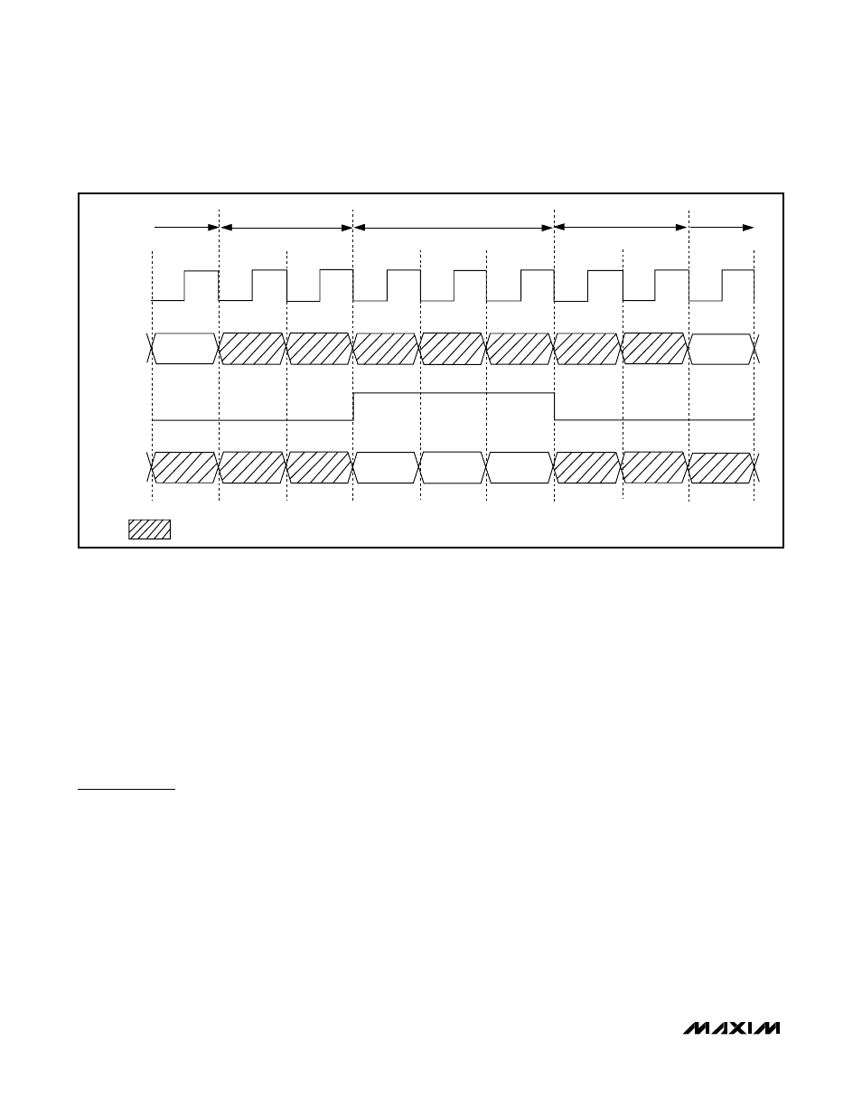
Transition Timing
The transition words require interconnect bandwidth
and displace control data. Therefore, control data is not
sampled (see Figure 9):
• Two clock cycles before DE_IN goes high.
• During the video phase.
• Two clock cycles after DE_IN goes low.
The last sampled control data are latched at the deserial-
izer control data outputs during the transition and video
phases. Video data are latched at the deserializer RGB
data outputs during the transition and control phases.
Applications Information
AC-Coupling Benefits
AC-coupling increases the common-mode voltage to
the voltage rating of the capacitor. Two capacitors are
sufficient for isolation, but four capacitors—two at the
serializer output and two at the deserializer input—pro-
vide protection if either end of the cable is shorted to a
high voltage. AC-coupling blocks low-frequency
ground shifts and common-mode noise. The MAX9217
serializer can also be DC-coupled to the MAX9218
deserializer.
Figure 10 shows an AC-coupled serializer and deserial-
izer with two capacitors per link, and Figure 11 is the
AC-coupled serializer and deserializer with four capaci-
tors per link.
Selection of AC-Coupling Capacitors
See Figure 12 for calculating the capacitor values for
AC-coupling, depending on the parallel clock frequen-
cy. The plot shows capacitor values for two- and four-
capacitor-per-link systems. For applications using less
than 18MHz clock frequency, use 0.125µF capacitors.
Frequency-Range Setting RNG[1:0]
The RNG[1:0] inputs select the operating frequency
range of the MAX9217 serializer. An external clock with-
in this range is required for operation. Table 3 shows
the selectable frequency ranges and corresponding
data rates for the MAX9217.
PCLK_IN
CNTL_IN
DE_IN
RGB_IN
= NOT SAMPLED BY PCLK_IN
CONTROL
PHASE
CONTROL
PHASE
TRANSITION
PHASE
TRANSITION
PHASE
VIDEO PHASE
Figure 9. Transition Timing