Detailed description, Pin description (continued) – Rainbow Electronics MAX9621 User Manual
Page 9
Dual, 2-Wire Hall-Effect Sensor Interface with
Analog and Digital Outputs
MAX9621
9
Detailed Description
The MAX9621, an interface between two 2-wire Hall-
effect sensors and a low-voltage microprocessor, sup-
plies and monitors current through IN1 and IN2 to two
Hall sensors.
The MAX9621 complements Maxim’s existing family of
Hall-effect sensor interfaces that includes the MAX9921.
The MAX9621 provides two independent channels with
two outputs for each channel, a digital output, and an
analog output. The digital outputs (DOUT1 and DOUT2)
are open-drain and indicate a logic level that corresponds
to the Hall sensor status. DOUT1 or DOUT2 outputs high
when the current out of IN1 or IN2, respectively, exceeds
the high-input current threshold. DOUT1 or DOUT2
outputs low when the current flowing out of IN1 or IN2,
respectively, is lower than the low-input current threshold.
DOUT1 and DOUT2 provide a time domain output filter
for robust noise immunity. See Figure 2.
The analog outputs (AOUT1 and AOUT2) mirror the cur-
rent flowing out to the corresponding inputs IN1 and IN2
with a nominal gain of 0.05mA/mA.
Hall Sensor Protection
from Supply Transients
The MAX9621 protects the hall sensors from supply
transients by shutting off current at IN1 and IN2 when
the BAT voltage is 18V. The digital outputs go low and
analog outputs have zero output current. When V
BAT
returns to the proper operating range, both inputs restart
following a blanking cycle.
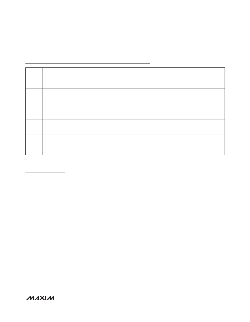
Pin Description (continued)
PIN
NAME
FUNCTION
6
DOUT2
Open-Drain Output. Signal translated from Hall sensor 2. DOUT2 is high when the current flowing out of
IN2 exceeds the input current threshold high, and is low when less than the input current threshold low.
See Table 1 for output response to operating conditions.
7
AOUT2
Analog Current Output. Mirrors the current to the corresponding Hall sensor at IN2. When IN2 has been
shut down due to a short to GND a current of zero is supplied to AOUT2. See Table 1 for output response
to operating conditions. To obtain a voltage output, connect a resistor from AOUT_ to ground.
8
DOUT1
Open-Drain Output. Signal translated from Hall sensor 1. DOUT1 is high when the current flowing out of
IN1 exceeds the input current threshold high, and is low when less than the input current threshold low.
See Table 1 for output response to operating conditions.
9
AOUT1
Analog Current Output. Mirrors the current to the corresponding Hall sensor at IN1. When IN1 has been
shut down due to a short to GND a current of zero is supplied to AOUT1. See Table 1 for output response
to operating conditions. To obtain a voltage output, connect a resistor from AOUT_ to ground.
10
SLEEP
Sleep Mode Input. The part is placed in sleep mode when the SLEEP input is low for more than 40Fs.
If the SLEEP input is low for less than 20Fs and then goes high, the part restarts any Hall input that has
been shut off due to a detected short to GND. Any Hall input that is operational is not affected when
SLEEP is cycled low for less than 20Fs. There is an internal 100kI pulldown resistance to GND.