Pin description pin configuration – Rainbow Electronics MAX9621 User Manual
Page 8
Dual, 2-Wire Hall-Effect Sensor Interface with
Analog and Digital Outputs
MAX9621
8
Pin Description
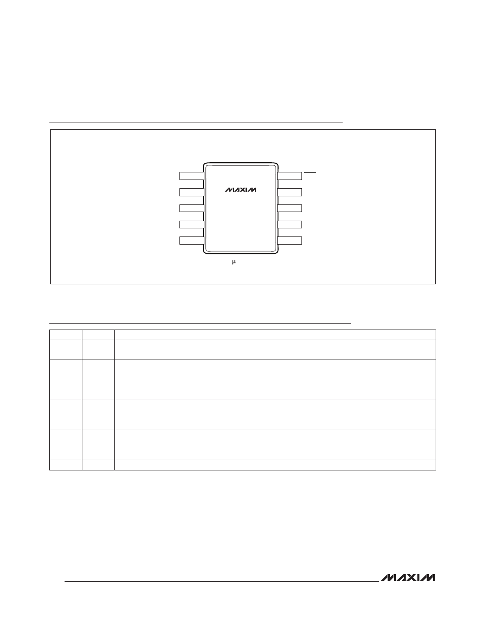
Pin Configuration
PIN
NAME
FUNCTION
1
BAT
Battery Power Supply. Connect to the positive supply through an external reverse-polarity diode.
Bypassed to GND with a 0.1FF capacitor.
2
ISET
Current Setting Input. Place a 1% resistor (R
SET
) between BAT and ISET to set the desired input current
threshold range for the DOUT_ outputs. See the Typical Operating Characteristics section for the correct
value of R
SET
for the desired range. Make no other connections to this pin. All routing must have low
parasitic capacitance. See the Input Current Thresholds and Short to Ground section.
3
IN1
Hall-Effect Sensor Input 1. Supplies current to the Hall sensor and monitors the current level drawn to
determine the high/low state of the sensor. Bypass to GND with a 0.01FF capacitor. Connect an unused
input to BAT pin.
4
IN2
Hall-Effect Sensor Input 2. Supplies current to the Hall sensor and monitors the current level drawn to
determine the high/low state of the sensor. Bypass to GND with a 0.01FF capacitor. Connect an unused
input to BAT pin.
5
GND
Ground
BAT
SLEEP
AOUT1
DOUT1
AOUT2
DOUT2
IN2
GND
ISET
IN1
µMAX
TOP VIEW
+
MAX9621
1
4
5
2
3
10
9
8
7
6