Dc electrical characteristics, Absolute maximum ratings – Rainbow Electronics MAX9621 User Manual
Page 2
Dual, 2-Wire Hall-Effect Sensor Interface with
Analog and Digital Outputs
MAX9621
2
Stresses beyond those listed under “Absolute Maximum Ratings” may cause permanent damage to the device. These are stress ratings only, and functional
operation of the device at these or any other conditions beyond those indicated in the operational sections of the specifications is not implied. Exposure to absolute
maximum rating conditions for extended periods may affect device reliability.
BAT to GND ...........................................................-0.3V to +60V
ISET to BAT ..........................................................-2.0V to +0.3V
IN1, IN2 to GND ................ -3V to lower of +60V or (V
BAT
+ 1V)
AOUT1, DOUT1, AOUT2, DOUT2,
SLEEP to GND .....................................................-0.3V to +6V
Short-Circuit Duration
AOUT1, DOUT1, AOUT2, DOUT2 to GND
or to 5.5V (individually) .......................................Continuous
Current In to IN1, IN2 .................................................... ±100mA
Current In to Any Other Pin ............................................. ±20mA
Continuous Power Dissipation for a S
ingle-Layer Board
(T
A
= +70NC)
10-Pin µMAX (derate 5.6mW/NC) above +70NC........444.4mW
Continuous Power Dissipation for a Multil
ayer Board
(T
A
= +70NC)
10-Pin µMAX (derate 8.8mW/NC) above +70NC........707.3mW
Operating Temperature Range ........................ -40NC to +125NC
Junction Temperature .....................................................+150NC
Storage Temperature Range ............................ -65NC to +160NC
Lead Temperature (soldering, 10s) ................................+300NC
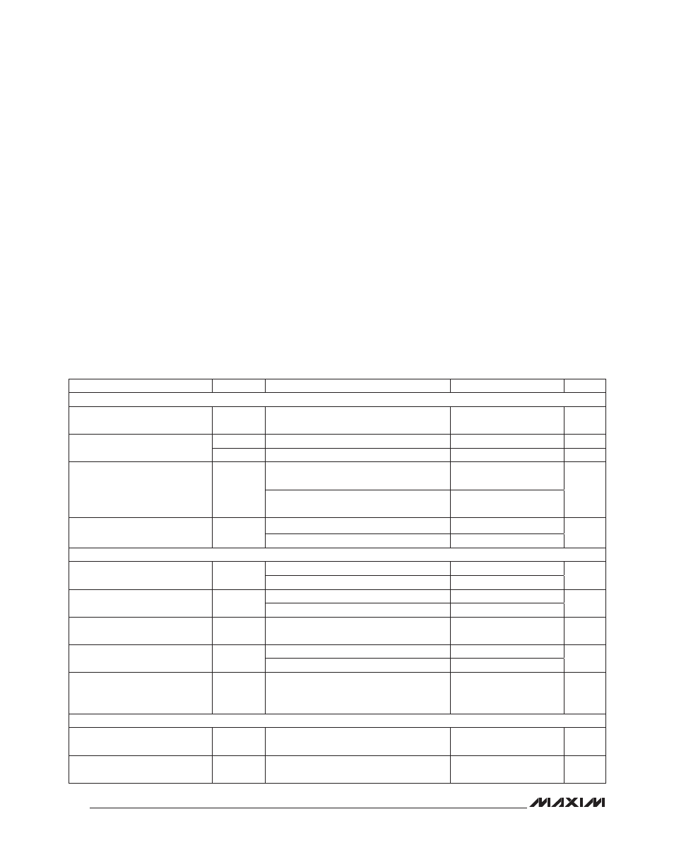
DC ELECTRICAL CHARACTERISTICS
(V
BAT
= 13.6V, V
SLEEP
= 5V, IN1 = IN2 = no connection, R
SET
= 61.9kI to BAT, R
PU
= 10kI at DOUT1 and DOUT2, R
L
= 5kI to
GND at AOUT1 and AOUT2, unless otherwise noted, T
A
= -40NC to +125NC. Typical values are at T
A
= +25NC.) (Note 1)
ABSOLUTE MAXIMUM RATINGS
PARAMETER
SYMBOL
CONDITIONS
MIN
TYP
MAX
UNITS
GENERAL
BAT Supply Range
V
BAT
Guaranteed by functional test of I
IH
, I
IL
,
and G
EI
5.5
18
V
BAT Supply Current
I
BAT
Normal mode
1
mA
I
SD
V
SLEEP
= 0V
1
10
F
A
Hall Input Voltage Dropout
V
DO
V
BAT
= 5.5V, at IN1 and IN2,
I
IN
= -14mA
0.59
1.26
V
V
BAT
= 5.5V, at IN1 and IN2,
I
IN
= -20mA
0.86
1.86
ESD Protection
Machine Model
±200
V
Human Body Model
±2000
INPUT THRESHOLDS FOR DOUT1, DOUT2 SWITCHING
Input Current for Output High
(Note 2)
I
IH
R
SET
= 95.3kI
-7.7
mA
R
SET
= 52.3kI
-14
Input Current for Output Low
(Note 2)
I
IL
R
SET
= 95.3kI
-5
mA
R
SET
= 52.3kI
-9
Input Current Hysteresis for
High/Low Detection
I
IN_HYS
Peak-to-peak as percent of average high/
low threshold (Note 2)
8
%
Channel-to-Channel Input
Threshold Variation
High threshold
0.02
mA
Low threshold
0.02
Short-Circuit Current Limit
I
SC
A short to GND is not a sustained
condition, Hall input reverts to -50FA when
detected (Note 2)
-20
mA
AOUT1, AOUT2 ANALOG OUTPUTS
Current Gain for AOUT1 and
AOUT2 Outputs
G
I
-18mA P I
IN
P -2mA
0.05
mA/mA
Current Gain Error for AOUT1
and AOUT2 Outputs
G
EI
I
IN
= -5mA, -14mA
0.2
±1.7
%