Application information – Rainbow Electronics MAX9621 User Manual
Page 11
Dual, 2-Wire Hall-Effect Sensor Interface with
Analog and Digital Outputs
MAX9621
11
Sleep Mode Input (SLEEP)
The MAX9621 features an active-low SLEEP input. Pull
SLEEP low for more than 40Fs to put the device into
sleep mode for power saving. In sleep mode, the DOUT1
and DOUT2 outputs are high impedance and are pulled
high by pullup resistors. AOUT1 and AOUT2 are set to
zero-output current.
Hall Input Restart
When an input has been shut down due to a short to
ground, cycle SLEEP for 10Fs to 20Fs to restart the input.
If the other input is operational it is not affected. The
restart happens on the rising edge of SLEEP.
Input Current Thresholds and
Short to Ground
The input current high and low thresholds that determine
the logic level of the digital outputs are adjusted by
changing the R
SET
value. When the R
SET
value changes,
the following parameters change as well: I
IN_HYS
, I
SC
,
t
BL
, t
RAMP
, t
DEL
, f
MAX,
and P
R
.
I
IH
, I
IL
, I
IN_HYS
, I
SC
, t
RAMP
, and f
MAX
are inversely pro-
portional to R
SET
and decrease as R
SET
increases. This
inverse relationship is linear. For example, a 10% change in
(1/R
SET
) results in a 10% change in current parameters.
Conversely, time and delay parameters are linear and
directly proportional to R
SET
, and a 10% change in R
SET
results in an 10% change in time parameters.
The difference between the maximum and minimum
threshold current limits is the min/max limit spread, which
is greater than the threshold hysteresis. The min/max
spread and the hysteresis both change by the same per-
centage as the mean of the threshold current limits. The
following equation is useful for finding the mean of the
threshold current limits given a value of R
SET
resistance:
(
)
0
1
I I
I 0
R m
=
+
<
×
I is the mean of the threshold current limits, R is
the value of the R
SET
resistance in kΩ, the constant
I
0
= 0.03717mA, and the constant m = -0.001668
(1/(kΩ x mA)).
The following equation is useful for finding the value of
R
SET
resistance given a mean of the threshold current
limits:
(
)
0
Y Y
m I I 0
1
R
Y
=
+
×
<
=
Y
0
= 6.2013 x 10
-5
units of (1/kΩ)
To compute the typical input current thresholds from the
mean input current, it is necessary to obtain the hyster-
esis. The following equation finds the hysteresis given
the mean threshold current, I:
H = H
0
+ k x I (I < 0)
where H
0
= -0.033463 in mA, and k = -0.08414 in mA/mA.
Input current threshold high = I - H/2, input current
threshold low = I + H/2.
Application Information
Use of Digital and Analog Outputs
The digital output can be used to provide the FP with an
interrupt signal that can represent a Hall sensor change
of status. DOUT1 and DOUT2 provide a time domain
output filter for robust noise immunity. See Figure 2.
The analog output can be connected to an ADC with an
appropriate load resistor, and can be used to perform
custom diagnostics.
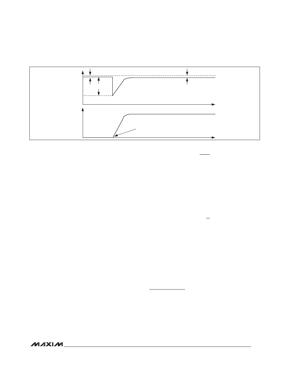
Figure 4. Hall Input Reenergized When Open Input Is Reconnected to Hall Sensor
14V
V
IN_
8V
5mA/
µs
HALL INPUT RECONNECTED
TO HALL SENSOR
11.5mA
I
IN_
0V
0A
TIME
TIME
V
BAT
- 500mV
V
BAT
- 25mV