Rainbow Electronics MAX6796 User Manual
Page 18
MAX6791–MAX6796
High-Voltage, Micropower, Single/Dual Linear
Regulators with Supervisory Functions
18
______________________________________________________________________________________
Selecting Watchdog Timeout Period
The watchdog timeout period is adjustable to accommo-
date a variety of µP applications. With this feature, the
watchdog timeout can be optimized for software execu-
tion. The programmer can determine how often the
watchdog timer should be serviced. Adjust the watch-
dog timeout period (t
WD
) by connecting a capacitor
between CSWT and GND. For normal-mode operation,
calculate the watchdog timeout capacitor as follows:
where t
WD
is in seconds and C
CSWT
is in Farads.
To select the internally fixed watchdog timeout period
for the MAX6791–MAX6794, connect CSWT to OUT1.
To select the internally fixed watchdog timeout period
for the MAX6795/MAX6796, connect CSWT to OUT.
Driving CSWT low disables the watchdog timer.
C
CSWT
must be a low-leakage (< 10nA) type capacitor.
Ceramic capacitors are recommended; do not use
capacitors lower than 100pF to avoid the influence of
parasitic capacitances.
The MAX6791/MAX6792 have a windowed watchdog
timer that asserts RESET for t
RP
when the watchdog
recognizes a fast watchdog fault (time between transi-
tions < t
WD1
), or a slow watchdog fault (time between
transitions > t
WD2
). The reset timeout period is adjust-
ed independently of the watchdog timeout period. The
slow watchdog period, t
WD2
, is calculated as follows:
where t
WD2
is in seconds and C
CSWT
is in Farads.
The fast watchdog period, t
WD1
, is selectable as a ratio
from the slow watchdog fault period (t
WD2
). Select the
fast watchdog period by connecting WDS0 and WDS1 to
OUT/OUT1 or GND according to Table 4, which illus-
trates the settings for the 8, 16, and 64 window ratios
(t
WD2
/t
WD1
). For example, if C
CSWT
is 2000pF, and
WDS0 and WDS1 are low, then t
WD2
is 318ms (typ) and
t
WD1
is 40ms (typ). RESET asserts if the watchdog input
has two edges too close to each other (faster than t
WD1
);
or has edges that are too far apart (slower than t
WD2
).
All WDI inputs are ignored while RESET is asserted. The
watchdog timer begins to count after RESET is
deasserted. If the time difference between two transi-
tions on WDI is shorter than t
WD1
or longer than t
WD2
,
RESET is forced to assert low for the reset timeout peri-
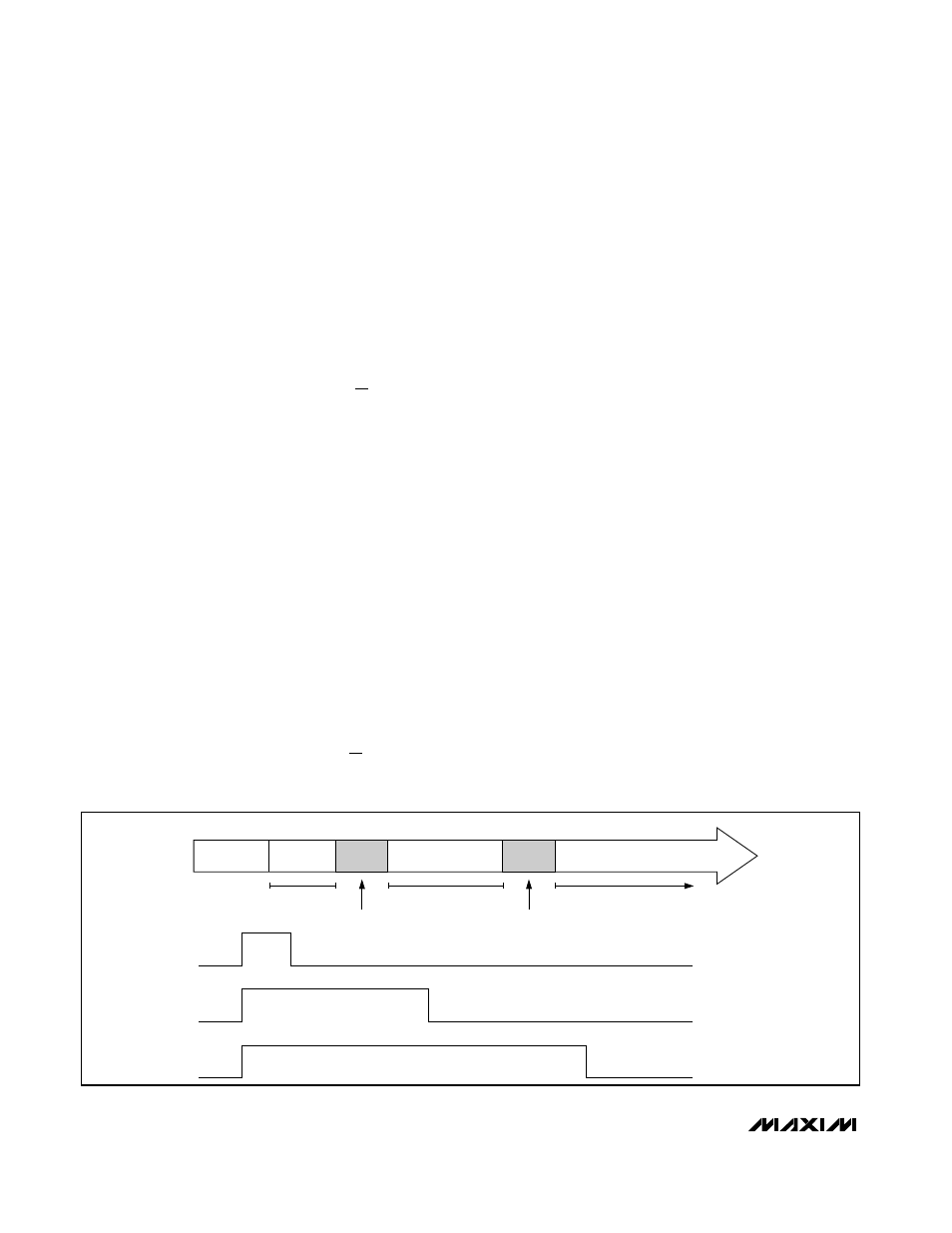
od. If the time difference between two transitions on WDI
is between t
WD1
(min) and t
WD1
(max) or t
WD2
(min)
and t
WD2
(max), RESET is not guaranteed to assert or
deassert; see Figure 3. To guarantee that the window
watchdog does not assert RESET, strobe WDI between
t
WD1
(max) and t
WD2
(min). The watchdog timer is
cleared when RESET is asserted. Disable the watchdog
timer by connecting WDS0 high and WDS1 low.
There are several options available to disable the
watchdog timer (for system development or test pur-
poses or when the µP is in a low-power sleep mode).
One way to disable the watchdog timer is to drive
WD-DIS low for the MAX6793–MAX6796 and drive
WDS0 high and WDS1 low for the MAX6791/MAX6792.
Another method of disabling the watchdog timer is to
pull CSWT low with an open-drain driver stage. This
prevents the capacitor from ramping up. Finally, reduc-
ing the OUT/OUT1 regulator current below the speci-
fied regulator current watchdog-disable threshold (3mA
min) also disables the watchdog timer. The watchdog
t
C
V
A
WD
CSWT
2
6
155
10
=
×
t
C
V
A
WD
CSWT
2
6
155
10
=
×
t
WD1
t
WD2
t
WD0
MIN
GUARANTEED
TO ASSERT
UNDETERMINED
UNDETERMINED
GUARANTEED
TO NOT ASSERT
GUARANTEED
TO ASSERT
FAST
FAULT
NORMAL
OPERATION
SLOW
FAULT
RESET:
WDI INPUT:
MAX
MIN
MAX
Figure 3. Windowed Watchdog Timing Diagram