Pin description (continued) – Rainbow Electronics MAX6796 User Manual
Page 11
MAX6791–MAX6796
High-Voltage, Micropower, Single/Dual Linear
Regulators with Supervisory Functions
______________________________________________________________________________________
11
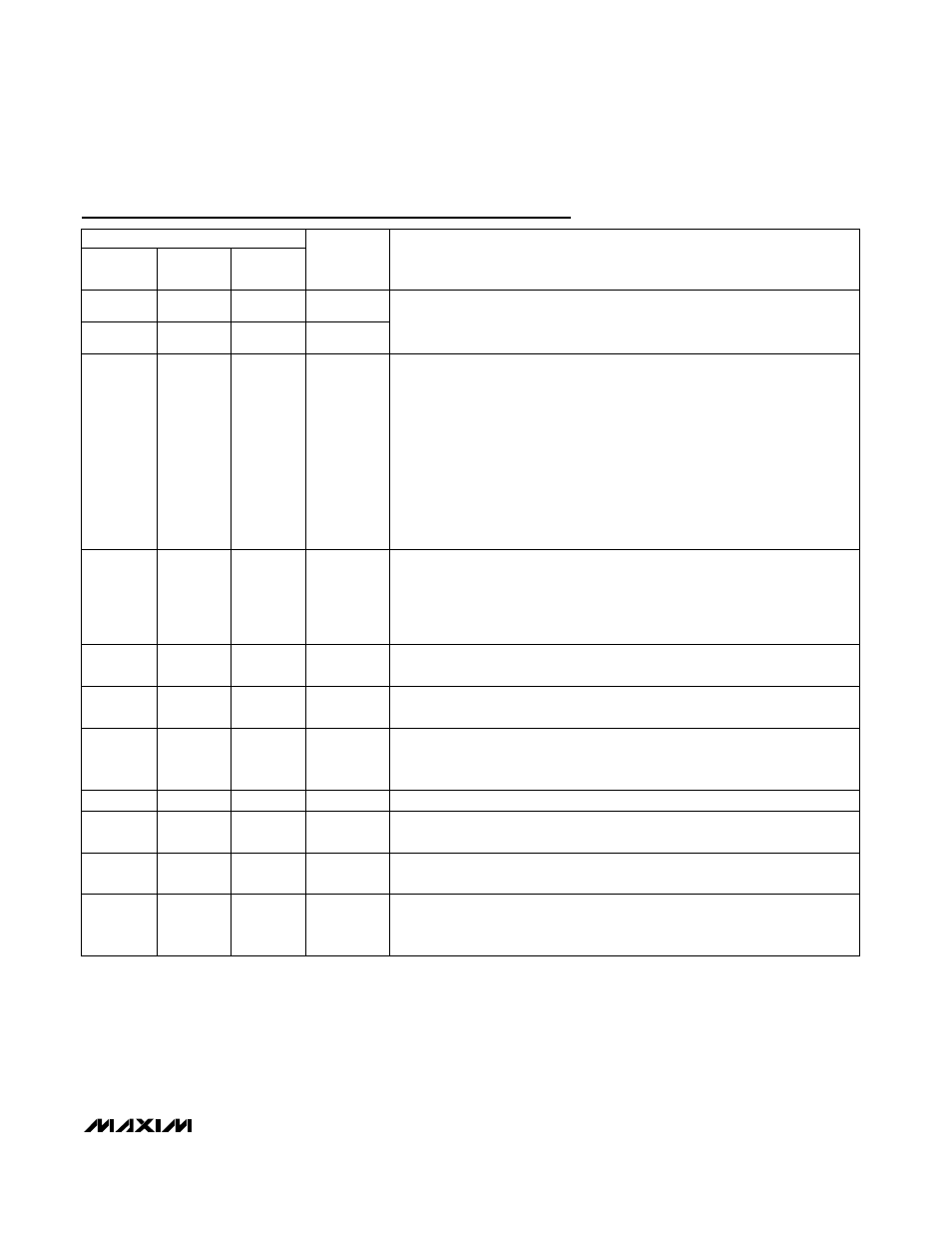
Pin Description (continued)
PIN
MAX6791/
MAX6792
MAX6793/
MAX6794
MAX6795/
MAX6796
NAME
FUNCTION
9
—
—
WDS1
10
—
—
WDS0
Min/Max Watchdog Logic-Select Input. WDS0 and WDS1 select the watchdog
window ratio or disable the watchdog timer. Drive WDS0 and WDS1 high or
low to select the desired ratio, see Table 4.
11
11
11
WDI
Watchdog Input.
M AX 6793–M AX 6796: A fal l i ng or r i si ng tr ansi ti on m ust occur on W D I w i thi n the
sel ected w atchd og ti m eout p er i od or a r eset p ul se occur s. The w atchd og ti m er
cl ear s w hen a tr ansi ti on occur s on WD I or whenever RESET i s asser ted . C onnect
C S W T to g r ound to d i sab l e the w atchd og ti m er functi on.
MAX6791/MAX6792: W D I fal l i ng and r i si ng tr ansi ti ons w i thi n p er i od s shor ter than
t
WD 1
or l ong er than t
WD 2
force RESET to asser t l ow for the r eset ti m eout p er i od .
The w atchd og ti m er b eg i ns to count after RESET i s d easser ted . The w atchd og
ti m er cl ear s w hen a val i d tr ansi ti on occur s on W D I or w henever RES ET i s
asser ted . C onnect W D S 0 hi g h and WD S 1 l ow to d i sab l e the w atchd og ti m er
functi on. S ee the W atchd og Ti m er secti on.
12
12
12
HOLD
Active-Low Regulator Hold Input. When HOLD is forced low, OUT1/OUT
remains ON even if ENABLE1/ENABLE is pulled low. To shut down the output
of the regulator (OUT/OUT1), release HOLD after ENABLE1/ENABLE is pulled
low. Connect HOLD to OUT1/OUT or leave unconnected if unused. HOLD is
internally connected to OUT/OUT1 through a 2µA current source.
13, 14
13, 14
—
OUT2
Regulator 2 Output. OUT2 is a fixed +5V output. Connect a 10µF (min)
capacitor from OUT2 to GND.
15
15
—
ENABLE2
Active-High Enable Input 2. Drive ENABLE2 high to turn on OUT2. ENABLE2 is
internally connected to ground through a 0.5µA current sink.
16
16
16
PFI
Adjustable Power-Fail Comparator Input. Connect PFI to a resistive-divider to
set the desired PFI threshold. The PFI input is referenced to an accurate
1.231V threshold.
17, 18
17, 18
17, 18
IN
Reg ul ator Inp uts. Byp ass IN w i th a 1µF cap aci tor to G N D .
19
19
19
GATEP
pFET Gate Drive. Connect GATEP to the gate of a p-channel MOSFET to
provide low drop reverse-battery voltage protection.
20
20
—
ENABLE1
Active-High Enable Input 1. Drive ENABLE1 high to turn on OUT1. ENABLE1 is
internally connected to ground through a 0.5µA current sink.
—
9
9
WD-DIS
Watchdog Disable Input. Drive WD-DIS low to disable the watchdog timer.
Drive WD-DIS high or connect to OUT/OUT1 to enable the watchdog timer.
The watchdog timer clears when reset asserts.