Rainbow Electronics MAX6696 User Manual
Page 9
uration byte register. Hardware and software standbys
are very similar; all data is retained in memory, and the
SMBus interface is alive and listening for SMBus com-
mands but the SMBus timeout is disabled. The only dif-
ference is that in software standby mode, the one-shot
command initiates a conversion. With hardware stand-
by, the one-shot command is ignored. Activity on the
SMBus causes the device to draw extra supply current.
Driving STBY low overrides any software conversion
command. If a hardware or software standby command
is received while a conversion is in progress, the con-
version cycle is interrupted, and the temperature regis-
ters are not updated. The previous data is not changed
and remains available.
SMBus Digital Interface
From a software perspective, the MAX6695/MAX6696
appear as a series of 8-bit registers that contain tem-
perature data, alarm threshold values, and control bits.
A standard SMBus-compatible 2-wire serial interface is
used to read temperature data and write control bits
and alarm threshold data. The same SMBus slave
address provides access to all functions.
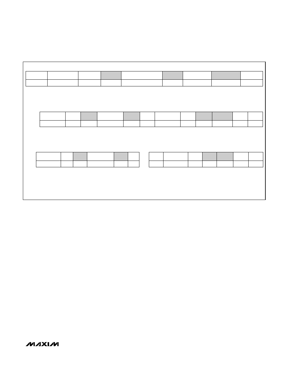
The MAX6695/MAX6696 employ four standard SMBus
protocols: Write Byte, Read Byte, Send Byte, and
Receive Byte (Figure 2). The shorter Receive Byte proto-
col allows quicker transfers, provided that the correct
data register was previously selected by a Read Byte
instruction. Use caution with the shorter protocols in mul-
timaster systems, since a second master could overwrite
the command byte without informing the first master.
When the conversion rate control register is set
≥ 06h,
temperature data can be read from the read internal
temperature (00h) and read external temperature (01h)
registers. The temperature data format in these regis-
ters is 7 bits + sign in two’s-complement form for each
channel, with the LSB representing 1°C (Table 2). The
MSB is transmitted first. Use bit 3 of the configuration
register to select the registers corresponding to remote
1 or remote 2.
When the conversion rate control register is set
≤ 05h,
temperature data can be read from the read internal
temperature (00h) and read external temperature (01h)
registers, the same as for faster conversion rates. An
additional 3 bits can be read from the read external
extended temperature register (10h) and read internal
MAX6695/MAX6696
Dual Remote/Local Temperature Sensors with
SMBus Serial Interface
_______________________________________________________________________________________
9
Figure 2. SMBus Protocols
ACK
7 bits
ADDRESS
ACK
WR
8 bits
DATA
ACK
1
P
8 bits
S
COMMAND
Write Byte Format
Read Byte Format
Send Byte Format
Receive Byte Format
Slave Address: equiva-
lent to chip-select line of
a 3-wire interface
Command Byte: selects which
register you are writing to
Data Byte: data goes into the register
set by the command byte (to set
thresholds, configuration masks, and
sampling rate)
ACK
7 bits
ADDRESS
ACK
WR
S
ACK
8 bits
DATA
7 bits
ADDRESS
RD
8 bits
///
P
COMMAND
Slave Address: equiva-
lent to chip-select line
Command Byte: selects
which register you are
reading from
Slave Address: repeated
due to change in data-
flow direction
Data Byte: reads from
the register set by the
command byte
ACK
7 bits
ADDRESS
WR
8 bits
COMMAND
ACK
P
ACK
7 bits
ADDRESS
RD
8 bits
DATA
///
P
S
Command Byte: sends com-
mand with no data, usually
used for one-shot command
Data Byte: reads data from
the register commanded
by the last Read Byte or
Write Byte transmission;
also used for SMBus Alert
Response return address
S = Start condition
Shaded = Slave transmission
P = Stop condition
/// = Not acknowledged