Rainbow Electronics MAX6696 User Manual
Page 7
and 100µA, the change in the measured voltage due to
series resistance is:
Since 1°C corresponds to 198.6µV, series resistance
contributes a temperature offset of:
Assume that the sensing diode being measured has a
series resistance of 3
Ω. The series resistance con-
tributes a temperature offset of:
The effects of the ideality factor and series resistance
are additive. If the diode has an ideality factor of 1.002
and series resistance of 3
Ω, the total offset can be cal-
culated by adding error due to series resistance with
error due to ideality factor:
1.36°C - 2.13°C = -0.77°C
for a diode temperature of +85°C.
3
0 453
1 36
Ω
Ω
×
° = +
°
.
.
C
C
90
198 6
0 453
µ
µ
V
V
C
C
Ω
Ω
.
.
°
=
°
∆V
A
A
R
A R
M
S
S
=
−
Ч
=
Ч
(
)
100
10
90
µ
µ
µ
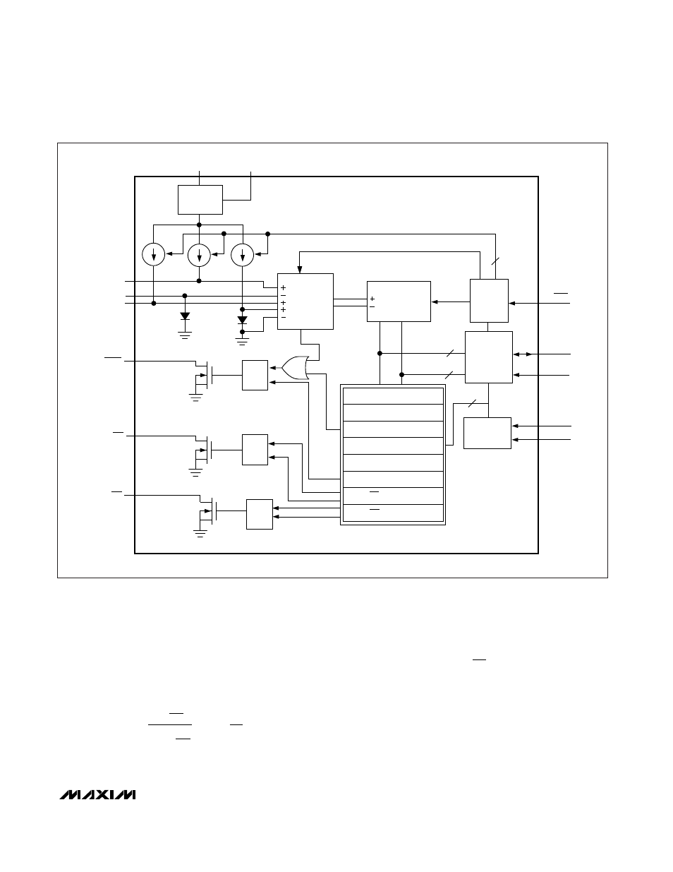
MAX6695/MAX6696
Dual Remote/Local Temperature Sensors with
SMBus Serial Interface
_______________________________________________________________________________________
7
OT2
OT1
ALERT
DXP2
DXN
DXP1
RESET/
UVLO
CIRCUITRY
V
CC
(RESET)
MUX
REMOTE1
REMOTE2
LOCAL
Q
S
R
OT2 THRESHOLDS
ALERT RESPONSE ADDRESS
ALERT THRESHOLD
LOCAL TEMPERATURES
REMOTE TEMPERATURES
COMMAND BYTE
REGISTER BANK
Q
S
R
Q
S
R
ADC
CONTROL
LOGIC
8
8
SMBus
READ
WRITE
(STBY)
SMBDATA
SMBCLK
(ADD0)
(ADD1)
ADDRESS
DECODER
3
DIODE FAULT
() ARE FOR MAX6696 ONLY.
7
OT1 THRESHOLDS
Figure 1. MAX6695/MAX6696 Functional Diagram