Pc board layout – Rainbow Electronics MAX6696 User Manual
Page 16
MAX6695/MAX6696
PC Board Layout
Follow these guidelines to reduce the measurement
error when measuring remote temperature:
1) Place the MAX6695/MAX6696 as close as is practi-
cal to the remote diode. In noisy environments, such
as a computer motherboard, this distance can be
4in to 8in (typ). This length can be increased if the
worst noise sources are avoided. Noise sources
include CRTs, clock generators, memory buses, and
PCI buses.
2) Do not route the DXP-DXN lines next to the deflec-
tion coils of a CRT. Also, do not route the traces
across fast digital signals, which can easily intro-
duce +30°C error, even with good filtering.
3) Route the DXP and DXN traces in parallel and in
close proximity to each other. Each parallel pair of
traces (DXP1 and DXN or DXP2 and DXN) should go
to a remote diode. Connect the two DXN traces at
the MAX6695/MAX6696. Route these traces away
from any higher voltage traces, such as +12VDC.
Dual Remote/Local Temperature Sensors with
SMBus Serial Interface
16
______________________________________________________________________________________
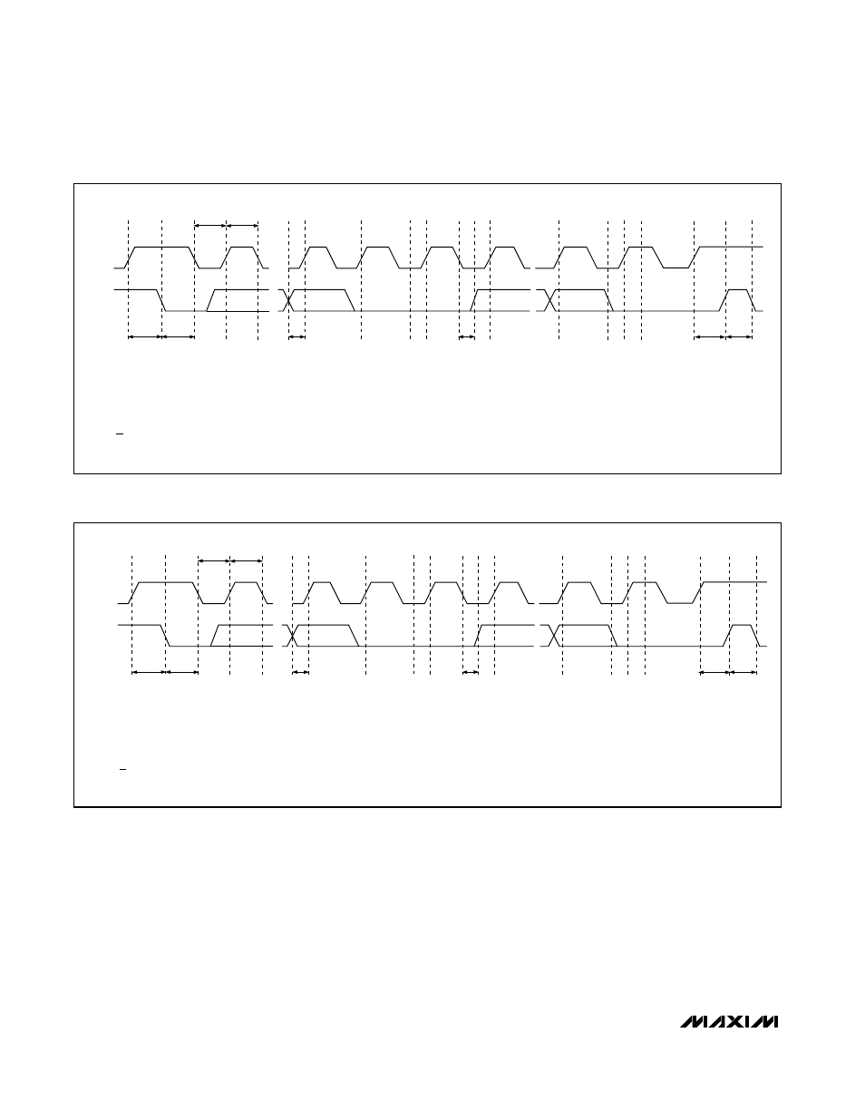
SMBCLK
A
B
C
D
E
F
G
H
I
J
K
SMBDATA
t
SU:STA
t
HD:STA
t
LOW
t
HIGH
t
SU:DAT
t
HD:DAT
t
SU:STO
t
BUF
A = START CONDITION
B = MSB OF ADDRESS CLOCKED INTO SLAVE
C = LSB OF ADDRESS CLOCKED INTO SLAVE
D = R/W BIT CLOCKED INTO SLAVE
E = SLAVE PULLS SMBDATA LINE LOW
L
M
F = ACKNOWLEDGE BIT CLOCKED INTO MASTER
G = MSB OF DATA CLOCKED INTO SLAVE
H = LSB OF DATA CLOCKED INTO SLAVE
I = MASTER PULLS DATA LINE LOW
J = ACKNOWLEDGE CLOCKED INTO SLAVE
K = ACKNOWLEDGE CLOCK PULSE
L = STOP CONDITION
M = NEW START CONDITION
Figure 3. SMBus Write Timing Diagram
SMBCLK
A
B
C
D
E
F
G
H
I
J
K
SMBDATA
t
SU:STA
t
HD:STA
t
LOW
t
HIGH
t
SU:DAT
t
HD:DAT
t
SU:STO
t
BUF
L
M
A = START CONDITION
B = MSB OF ADDRESS CLOCKED INTO SLAVE
C = LSB OF ADDRESS CLOCKED INTO SLAVE
D = R/W BIT CLOCKED INTO SLAVE
E = SLAVE PULLS SMBDATA LINE LOW
F = ACKNOWLEDGE BIT CLOCKED INTO MASTER
G = MSB OF DATA CLOCKED INTO MASTER
H = LSB OF DATA CLOCKED INTO MASTER
I = MASTER PULLS DATA LINE LOW
J = ACKNOWLEDGE CLOCKED INTO SLAVE
K = ACKNOWLEDGE CLOCK PULSE
L = STOP CONDITION
M = NEW START CONDITION
Figure 4. SMBus Read Timing Diagram