Pin description – Rainbow Electronics MAX6696 User Manual
Page 5
MAX6695/MAX6696
Dual Remote/Local Temperature Sensors with
SMBus Serial Interface
_______________________________________________________________________________________
5
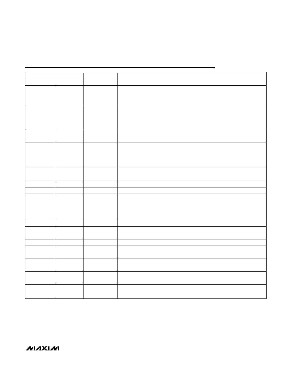
Pin Description
PIN
MAX6695
MAX6696
NAME
FUNCTION
1
2
V
CC
Supply Voltage Input, +3V to +3.6V. Bypass to GND with a 0.1µF capacitor. A
47
Ω series resistor is recommended but not required for additional noise
filtering. See Typical Operating Circuit.
2
3
DXP1
Combined Remote-Diode Current Source and A/D Positive Input for Remote-
Diode Channel 1. DO NOT LEAVE DXP1 FLOATING; connect DXP1 to DXN if no
remote diode is used. Place a 2200pF capacitor between DXP1 and DXN for
noise filtering.
3
4
DXN
Combined Remote-Diode Current Sink and A/D Negative Input. DXN is internally
biased to one diode drop above ground.
4
5
DXP2
Combined Remote-Diode Current Source and A/D Positive Input for Remote-
Diode Channel 2. DO NOT LEAVE DXP2 FLOATING; connect DXP2 to DXN if no
remote diode is used. Place a 2200pF capacitor between DXP2 and DXN for
noise filtering.
5
10
OT1
Overtemperature Active-Low Output, Open Drain. OT1 is asserted low only when
the temperature is above the programmed OT1 threshold.
6
8
GND
Ground
7
9
SMBCLK
SMBus Serial-Clock Input
8
11
ALERT
SMBus Alert (Interrupt) Active-Low Output, Open-Drain. Asserts when
temperature exceeds user-set limits (high or low temperature) or when a remote
sensor opens. Stays asserted until acknowledged by either reading the status
register or by successfully responding to an alert response address. See the
ALERT Interrupts section.
9
12
SMBDATA
SMBus Serial-Data Input/Output, Open Drain
10
13
OT2
Overtemperature Active-Low Output, Open Drain. OT2 is asserted low only when
temperature is above the programmed OT2 threshold.
—
1, 16
N.C.
No Connect
—
6
ADD1
SMBus Slave Address Select Input (Table 10). ADD0 and ADD1 are sampled
upon power-up.
—
7
RESET
Reset Input. Drive RESET high to set all registers to their default values (POR
state). Pull RESET low for normal operation.
—
14
ADD0
SMBus Slave Address Select Input (Table 10). ADD0 and ADD1 are sampled
upon power-up.
—
15
STBY
Hardware Standby Input. Pull STBY low to put the device into standby mode.
All registers’ data are maintained.