Electrical characteristics (continued) – Rainbow Electronics MAX6696 User Manual
Page 3
MAX6695/MAX6696
Dual Remote/Local Temperature Sensors with
SMBus Serial Interface
_______________________________________________________________________________________
3
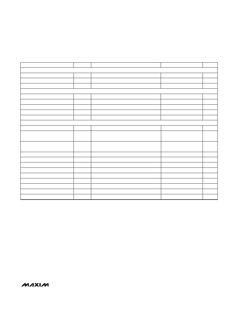
ELECTRICAL CHARACTERISTICS (continued)
(V
CC
= +3.0V to +3.6V, T
A
= 0°C to +125°C, unless otherwise noted. Typical values are at V
CC
= +3.3V and T
A
= +25°C)
PARAMETER
SYMBOL
CONDITIONS
MIN
TYP
MAX
UNITS
INPUT PIN, RESET,
STBY
(MAX6696)
Logic Input Low Voltage
V
IL
0.8
V
Logic Input High Voltage
V
IH
2.1
V
Input Leakage Current
I
LEAK
-1
+1
µA
SMBus INTERFACE (SMBCLK, SMBDATA,
STBY
)
Logic Input Low Voltage
V
IL
0.8
V
Logic Input High Voltage
V
IH
2.1
V
Input Leakage Current
I
LEAK
V
IN
= GND or V
CC
±1
µA
Output Low Sink Current
I
OL
V
OL
= 0.6V
6
mA
Input Capacitance
C
IN
5
pF
SMBus-COMPATIBLE TIMING
(Figures 4 and 5) (Note 2)
Serial Clock Frequency
f
SCL
10
100
kHz
Bus Free Time Between STOP
and START Condition
t
BUF
4.7
µs
Repeat START Condition Setup
Time
t
SU:STA
90% of SMBCLK to 90% of SMBDATA
4.7
µs
START Condition Hold Time
t
HD:STA
10% of SMBDATA to 90% of SMBCLK
4
µs
STOP Condition Setup Time
t
SU:STO
90% of SMBCLK to 90% of SMBDATA
4
µs
Clock Low Period
t
LOW
10% to 10%
4
µs
Clock High Period
t
HIGH
90% to 90%
4.7
µs
Data Setup Time
t
SU:DAT
250
µs
Data Hold Time
t
HD:DAT
300
µs
SMB Rise Time
t
R
1
µs
SMB Fall Time
t
F
300
ns
SMBus Timeout
SMBDATA low period for interface reset
20
30
40
ms
Note 1:
Based on diode ideality factor of 1.008.
Note 2:
Specifications are guaranteed by design, not production tested.