Rainbow Electronics MAX5735 User Manual
Page 22
MAX5732–MAX5735
32-Channel, 16-Bit, Voltage-Output
DACs with Serial Interface
22
______________________________________________________________________________________
W
WD2
W
WD1
W WD0
R
XX
R
XX
R
XX
X
XX
X
XX
X
XX
DIN(0)
CS
DOUT(0)
WD1
W
WD2
W
XX
R
XX
R
WD0
W
R RD0
X
XX
X
XX
DOUT(1)
W WD2
W
WD1
W
WD0
R
XX
R
RD1
R
RD0
X
XX
DOUT(2)
W WD2
W WD1
W WD0
R
RD2
R
RD1
R
RD0
W
WD2
R
XX
W WD0
R
XX
W
WD1
R
XX
X
XX
X
XX
X
XX
DIN(0)
CS
DOUT(0)
XX
R
WD2
W
WD1
W
XX
R
WD0
W
R
RD0
X
XX
X
XX
DOUT(1)
W WD2
R
RD1
W
WD0
R
XX
W
WD1
R
RD0
X
XX
DOUT(2)
W WD2
R
RD1
W WD0
R
RD2
W
WD1
R
RD0
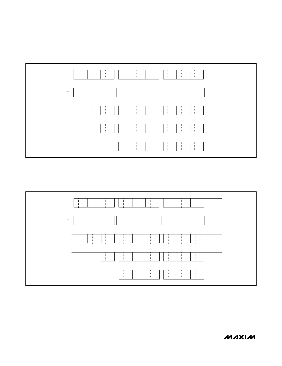
Figure 5. Example 1 of a Daisy-Chain Data Sequence
W/WD0 = 32-bit word with a write command; WD0 writes data for device 0. The 0 refers to the position in the daisy chain (0 is closest
to the bus master). Devices 1 and 2 are devices further down the chain.
R/RD2 = 32-bit word with a read command; RD2 reads data from device 2.
X = Don’t care (for X in the data or command position).
Figure 6. Example 2 of a Daisy-Chain Data Sequence
W/WD0 = 32-bit word with a write command; WD0 writes data for device 0. The 0 refers to the position in the daisy chain (0 is closest
to the bus master). Devices 1 and 2 are devices further down the chain.
R/RD2 = 32-bit word with a read command; RD2 reads data from device 2.
X = Don’t care (for X in the data or command position).