Rainbow Electronics MAX5735 User Manual
Page 21
MAX5732–MAX5735
32-Channel, 16-Bit, Voltage-Output
DACs with Serial Interface
______________________________________________________________________________________
21
SING
When SING = 0 (default power-up mode), the device is
in daisy-chain mode. DOUT follows DIN after 32 clock
cycles. For the read command, DOUT provides the
read data in the next cycle following
CS rising edge.
The 16 data bits of the previous command word are
clocked out on the last 16 clock cycles of the current
command word.
When SING = 1, the device is in stand-alone mode. To
reduce the time it takes to read data out, the read data is
provided at DOUT as the 16 data bits of the current com-
mand are clocked in. The device acts on an incoming
command word independent of the rising edge of
CS.
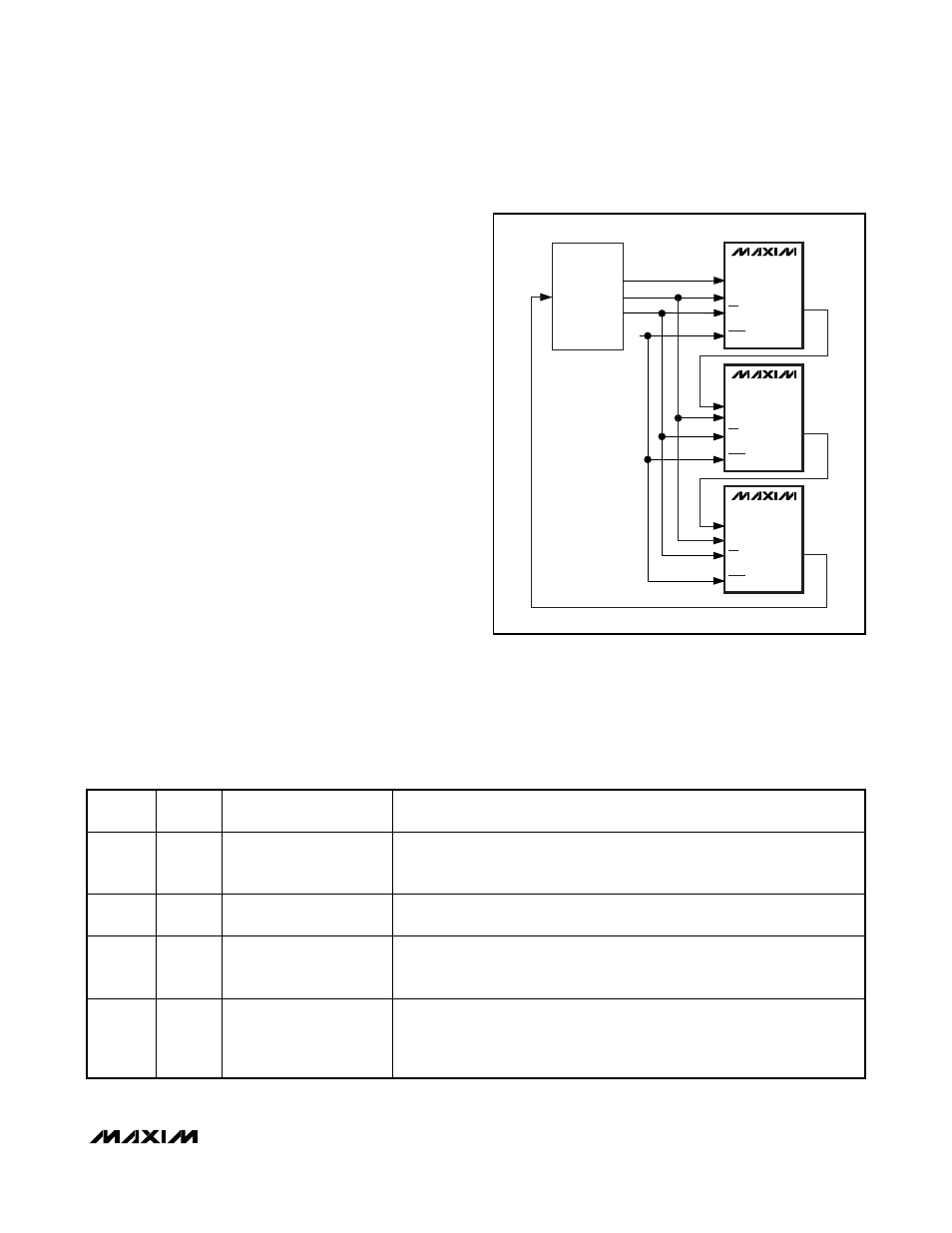
Daisy Chain Operation
Any number of the MAX5732–MAX5735 devices can be
daisy chained by connecting the DOUT of one device to
the DIN of another device in a chain. All devices must be
in SING = 0 mode. Connecting the
CS inputs of all
devices together eliminates the need to issue NOP com-
mands to devices early in the chain (see Figure 4).
Data Readback
The contents of the MAX5732–MAX5735 DAC and con-
figuration registers can be read on DOUT by issuing a
read-data command. Setting control bits C2, C1, and
C0 = 100, puts the device in read-data mode. The
address bits select the register to be read. The con-
tents of the register (16 data bits) are clocked out at
DOUT. The output-data format depends on the status of
DSP and SING. Table 10 shows the manner in which
data is written to DOUT. Note that when the device is in
DSP mode (
DSP = 0), only the 16-bit data of the selected
register is written to DOUT.
Table 10. Read-Data Modes with SING and
DSP Controls
DSP
SING
CONFIGURATION
DESCRIPTION
READ DATA AT DOUT
0
0
Stand alone
DOUT provides the 16 data bits from the previous command word. Data
appears at DOUT on the last 16 clock edges of the current command word.
See Figure 7.
0
1
Stand alone
D OU T p r ovi d es the 16 d ata b i ts fr om the cur r ent com m and w or d . D ata ap p ear s at
D OU T on the l ast 16 cl ock ed g es of the cur r ent com m and w or d . S ee Fi g ur e 7.
1
0
Daisy chain
Data on DOUT follows the current command word after 32 clock cycles. For
read commands, the read data from the previous command word appears at
DOUT on the last 16 clock edges of the current command word. See Figure 4.
1
1
Multiple DOUTs connected
in parallel (not daisy
chained)
DOUT provides the 16 data bits from the current command word. Data appears
at DOUT on the last 16 clock edges of the current command word. For read
commands, the read data from the current command word appears at DOUT
on the last 16 clock edges of the current command word. See Figures 8 and 9.
CONTROLLER
DEVICE
DIN(0)
DOUT(0)
1
SCLK
CS
DSP
MAX573_
DIN(1)
DOUT(1)
SCLK
CS
DSP
MAX573_
DIN(2)
DOUT(2)
SCLK
CS
DSP
MAX573_
Figure 4. Daisy-Chain Configuration