Table 9. configuration-register commands, Table 8. configuration-register data format – Rainbow Electronics MAX5735 User Manual
Page 20
MAX5732–MAX5735
32-Channel, 16-Bit, Voltage-Output
DACs with Serial Interface
20
______________________________________________________________________________________
DSP Mode (
DSP
)
The MAX5732–MAX5735 provide a hardware-selectable
DSP-interface mode. DSP mode, when active, allows
chip select (
CS) to go high before the entire 32-bit com-
mand word is clocked in. The active-low
DSP logic input
selects microcontroller (µC)- or DSP-interface mode.
Drive
DSP low for DSP-interface mode. Drive DSP high
for µC-interface mode. Figure 2 illustrates serial timing
for both µC- and DSP-interface modes.
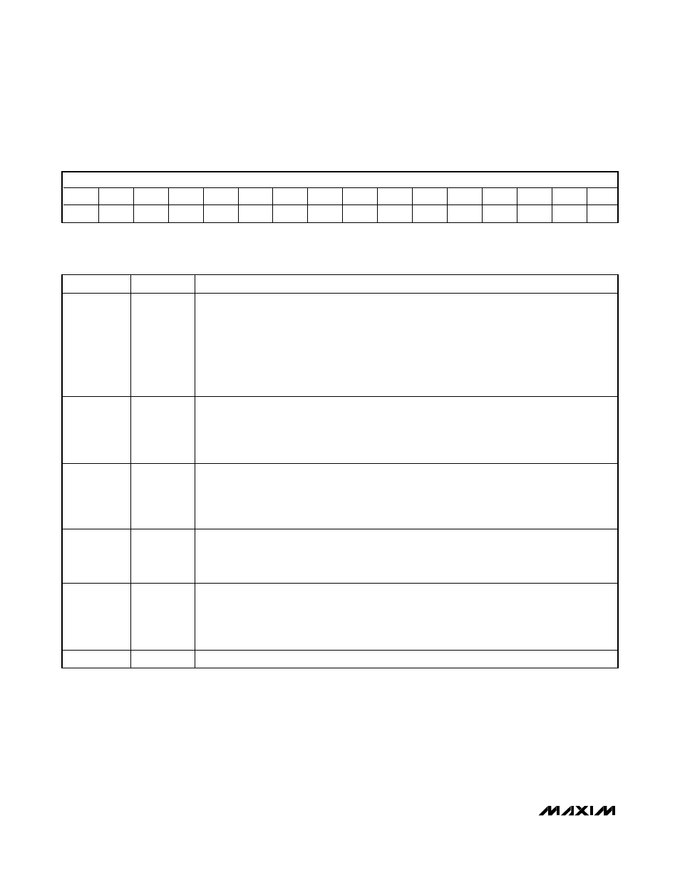
Configuration Register
The configuration register controls the advanced fea-
tures of the MAX5732–MAX5735. Write to the configura-
tion register by setting the control bits C2, C1, and C0
= 001 and address bits A5–A0 = 100001. Table 8
shows the configuration-register data format for the
D15–D0 data bits. Table 9 shows the commands con-
trolled by the configuration register.
Table 9. Configuration-Register Commands
DATA BIT
NAME
DESCRIPTION
D15
ERRF
Error flag; ERRF goes logic-high when an invalid command is attempted. ERRF is cleared each
time the configuration register is read back to DOUT. Clear-register commands C2, C1, and C0 =
111 resets ERRF. Conditions that trigger ERRF include:
Attempted read of address bits A5–A0 = 111111 (all 32 DACs)
Access to reserved addresses
Access to the configuration register (address bits A5–A0 = 100001 when used with control bits
C2, C1, and C0 = 010 and 011)
Default is logic-low (no error flags); ERRF is read only.
D14
SING
Single device; SING determines the manner in which data is output to DOUT. A logic-high sets the
device to operate in stand-alone mode or in parallel; only the 16 data bits are output to DOUT. A
logic-low sets the device to operate in a daisy chain of devices. In this case, the entire 32-bit
command word is output to DOUT.
Default is logic-low (daisy-chain mode); SING is read/write.
D13
GLT
Glitch-suppression enable; the MAX5732–MAX5735 feature glitch-suppression circuitry on the
analog outputs that minimizes the output glitch during a major carry transition. A logic-low disables
the internal glitch-suppression circuitry, which improves settling time. A logic-high enables glitch-
suppression, suppressing up to 120nV-s glitch impulse on the DAC outputs.
Default is logic-low (glitch suppression disabled); GLT is read/write.
D12
DT
Digital output enable; a logic-low enables DOUT. A logic-high disables DOUT. Disabling DOUT
reduces power consumption and digital noise feedthrough to the DAC outputs from the DOUT
output buffer.
Default is logic-low (DOUT enabled); DT is read/write.
D11
SHDN
Shutdown; a logic-high shuts down all 32 DACs. The logic interface remains active, and the data is
retained in the input and DAC registers. Read/write operations can be performed while the device
is disabled; however, no changes can occur at the device outputs. A logic-low powers up all 32
DACs if the device was previously in shutdown. Upon waking up, the DAC outputs return to the last
stored value in the DAC registers. Default is logic-low (normal operation); SHDN is read/write.
D10–D0
X
Don’t care.
Table 8. Configuration-Register Data Format
16 DATA BITS
D15
D14
D13
D12
D11
D10
D9
D8
D7
D6
D5
D4
D3
D2
D1
D0
ERRF
SING
GLT
DT
SHDN
X
X
X
X
X
X
X
X
X
X
X
X = Don’t care.