Typical operating characteristics, Electrical characteristics (continued) – Rainbow Electronics MAX9770 User Manual
Page 4
10
0.001
10
100
10k
100k
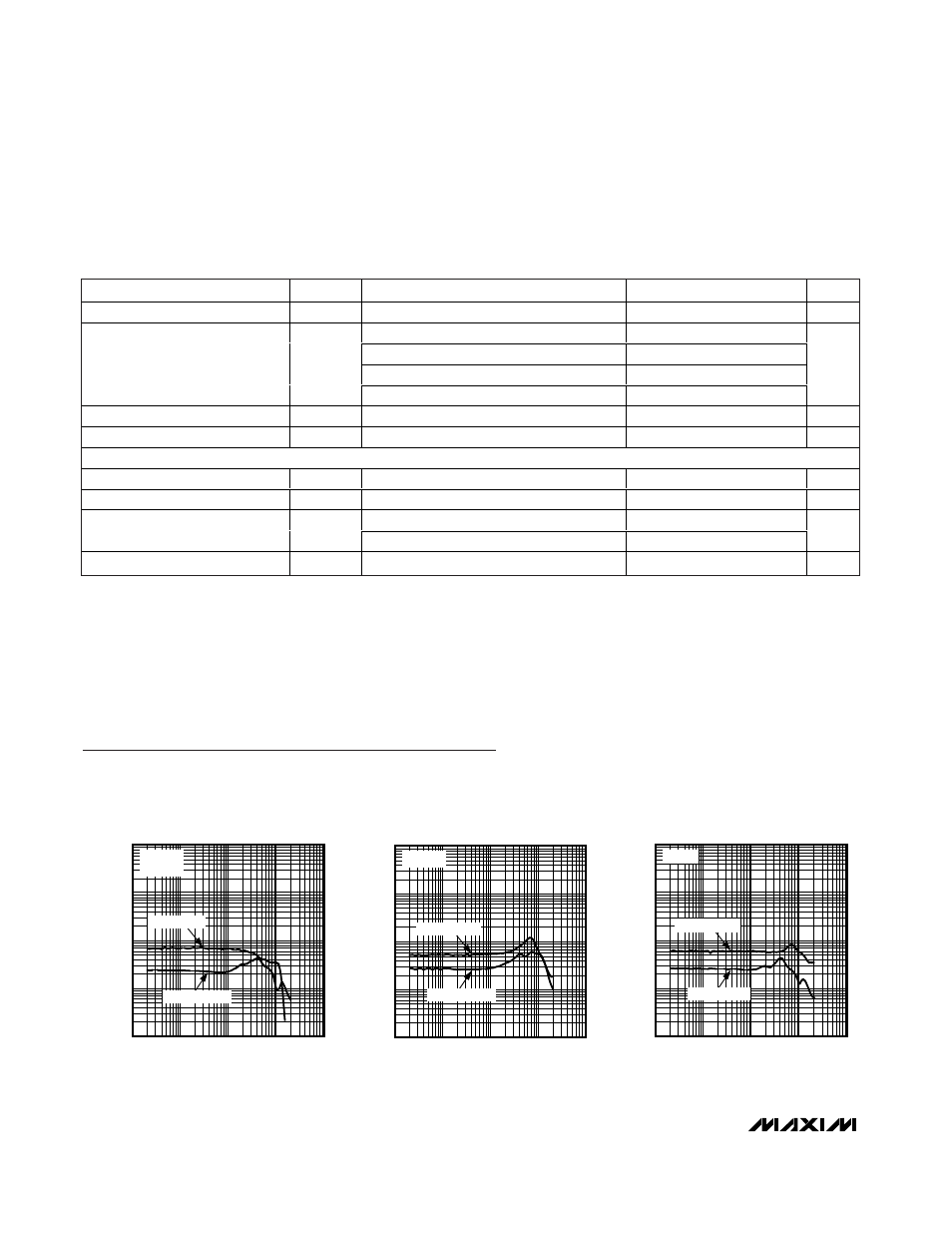
TOTAL HARMONIC DISTORTION PLUS NOISE
vs. FREQUENCY (SPEAKER MODE)
0.01
0.1
1
MAX9770 toc01
FREQUENCY (Hz)
THD+N (%)
1k
V
DD
= +5V
R
L
= 4
Ω
P
OUT
= 25mW
P
OUT
= 1000mW
10
0.001
10
100
10k
100k
TOTAL HARMONIC DISTORTION PLUS NOISE
vs. FREQUENCY (SPEAKER MODE)
0.01
0.1
1
MAX9770 toc02
FREQUENCY (Hz)
THD+N (%)
1k
R
L
= 4
Ω
P
OUT
= 100mW
P
OUT
= 500mW
10
0.001
10
100
10k
100k
TOTAL HARMONIC DISTORTION PLUS NOISE
vs. FREQUENCY (SPEAKER MODE)
0.01
0.1
1
MAX9770 toc03
FREQUENCY (Hz)
THD+N (%)
1k
R
L
= 8
Ω
P
OUT
= 40mW
P
OUT
= 400mW
Typical Operating Characteristics
(V
DD
= 3.3V, BW = 22Hz to 22kHz, GAIN1 = 1, GAIN2 = 0, spread-spectrum mode, headphone outputs in phase.)
MAX9770
1.2W Low-EMI, Filterless, Mono Class D Amplifier
with Stereo DirectDrive Headphone Amplifiers
4
_______________________________________________________________________________________
ELECTRICAL CHARACTERISTICS (continued)
(V
DD
= PV
DD
= CPV
DD
= 3.3V, GND = PGND = CPGND = 0V, SHDN = 3.3V, C1 = C2 = 1µF, C
BIAS
= 0.047µF, SYNC = GND, R
L
=
∞,
speaker load connected between OUT+ and OUT-, headphone load connected between HPOUT_ and GND, T
A
= T
MIN
to T
MAX
,
unless otherwise noted. Typical values are at T
A
= +25°C.) (Notes 1, 2)
PARAMETER
SYMBOL
CONDITIONS
MIN
TYP
MAX
UNITS
Capacitive-Load Drive
C
L
1000
pF
GAIN1 = 0, GAIN2 = 0
7
GAIN1 = 0, GAIN2 = 1
4
GAIN1 = 1, GAIN2 = 0
-2
Gain
A
V
GAIN1 = 1, GAIN2 = 1
1
dB
Gain Accuracy
±2.5
%
ESD Protection
HPOUTR, HPOUTL, IEC Air Discharge
±8
kV
DIGITAL INPUTS (
SHDN
, SYNC, HPS, GAIN_, SEL_)
Input Voltage High
V
IH
2
V
Input Voltage Low
V
IL
0.8
V
SYNC input
±25
Input Leakage Current
All other logic inputs
±1
µA
HPS Input Current
HPS = GND
-10
µA
Note 1:
All devices are 100% production tested at +25°C. All temperature limits are guaranteed by design.
Note 2:
Speaker amplifier testing performed with a resistive load in series with an inductor to simulate an actual speaker load. For
R
L
= 4
Ω, L = 47µH. For R
L
= 8
Ω, L = 68µH.
Note 3:
Guaranteed by design, not production tested.
Note 4:
PSRR is specified with the amplifier inputs connected to GND through C
IN
.