Table 1. operating modes – Rainbow Electronics MAX9770 User Manual
Page 11
MAX9770
1.2W Low-EMI, Filterless, Mono Class D Amplifier
with Stereo DirectDrive Headphone Amplifiers
______________________________________________________________________________________
11
OUT+
OUT-
V
IN-
V
IN+
V
OUT+
- V
OUT-
t
ON(MIN)
t
SW
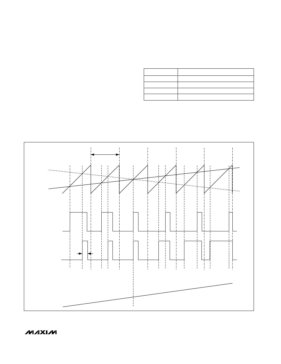
Figure 1. MAX9770 Outputs with an Input Signal Applied
width pulse t
ON(min)
at the output of the second com-
parator (Figure 1). As the input voltage increases or
decreases, the duration of the pulse at one output
increases (the first comparator trip point) while the
other output pulse duration remains at t
ON(min)
. This
causes the net voltage across the speaker (V
OUT+
-
V
OUT-
) to change.
Operating Modes
The switching frequency of the charge pump is 1/2 the
switching frequency of the Class D amplifier, regard-
less of the operating mode. When SYNC is driven exter-
nally, the charge pump switches at 1/2 f
SYNC
. When
SYNC = V
DD
, the charge pump switches with a spread-
spectrum pattern.
Fixed-Frequency Modulation (FFM) Mode
The MAX9770 features two FFM modes. The FFM
modes are selected by setting SYNC = GND for a
1.1MHz switching frequency, and SYNC = FLOAT for a
1.45MHz switching frequency. In FFM mode, the fre-
quency spectrum of the Class D output consists of the
SYNC INPUT
MODE
GND
FFPWM with f
S
= 1100kHz
FLOAT
FFPWM with f
S
= 1450kHz
V
DD
SSPWM with f
S
= 1220kHz
±120kHz
Clocked
FFPWM with f
S
= external clock frequency
Table 1. Operating Modes