Table 2. multiplexer/mixer settings – Rainbow Electronics MAX9770 User Manual
Page 15
inputs are attenuated by 6dB and mixed together, result-
ing in a true mono reproduction of a stereo signal. When
more than one signal path is selected, the sources are
attenuated before mixing to preserve overall amplitude.
Selecting two sources results in 6dB attenuation, select-
ing three sources results in 9.5dB attenuation.
Headphone Sense Input (HPS)
The headphone sense input (HPS) monitors the head-
phone jack, and automatically configures the device
based upon the voltage applied at HPS. A voltage of
less than 0.8V sets the device to speaker mode. A volt-
age of greater than 2V disables the bridge amplifiers
and enables the headphone amplifiers.
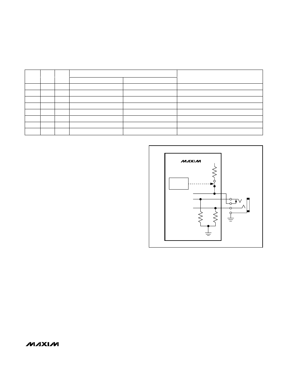
For automatic headphone detection, connect HPS to
the control pin of a 3-wire headphone jack as shown in
Figure 6. With no headphone present, the output
impedance of the headphone amplifier pulls HPS to
less than 0.8V. When a headphone plug is inserted into
the jack, the control pin is disconnected from the tip
contact and HPS is pulled to V
DD
through the internal
800k
Ω pullup. When driving HPS from an external logic
source, ground HPS when the MAX9770 is shut down.
Place a 10k
Ω resistor in series with HPS and the head-
phone jack to ensure ±8kV ESD protection.
Table 2 shows the output amplitude of the selected
channels multiplied by the gain.
BIAS
The MAX9770 features an internally generated, power-
supply independent, common-mode bias voltage refer-
enced to GND. BIAS provides both click-and-pop
suppression and sets the DC bias level for the amplifiers.
Choose the value of the bypass capacitor as described
in the BIAS Capacitor section. No external load should
be applied to BIAS. Any load lowers the BIAS voltage,
affecting the overall performance of the device.
Gain Selection
The MAX9770 features a logic-selectable, internally set
gain. GAIN1 and GAIN2 set the gain of the MAX9770
speaker and headphone amplifiers as shown in Table 3.
The MAX9770 can be configured to automatically
switch between two gain settings depending on
whether the device is in speaker or headphone mode.
By driving one or both gain inputs with HPS, the gain of
the device changes when a headphone is inserted or
removed. For example, the block diagram shows HPS
connected to GAIN2, while GAIN1 is connected to V
DD
.
In this configuration, the gain in speaker mode is 9dB,
while the gain in headphone mode is 1dB. The gain
settings with the HPS connection are shown in Table 4.
MAX9770
1.2W Low-EMI, Filterless, Mono Class D Amplifier
with Stereo DirectDrive Headphone Amplifiers
______________________________________________________________________________________
15
Table 2. Multiplexer/Mixer Settings
HEADPHONE MODE
SEL1
SEL2
SELM
HPOUTL
HPOUTR
SPEAKER MODE
0
0
0
MUTE
MUTE
MUTE
1
0
0
IN1_L
IN1_R
(IN1_L + IN1_R) / 2
0
1
0
IN2_L
IN2_R
(IN2_L + IN2_R) / 2
0
0
1
MONO
MONO
MONO
1
1
0
(IN1_L + IN2_L) / 2
(IN1_R + IN2_R) / 2
(IN1_L + IN1_R + IN2_L + IN2_R) / 4
1
0
1
(IN1_L + MONO) /2
(IN1_R + MONO) / 2
(IN1_L + IN1_R + MONO x 2) / 4
0
1
1
(IN2_L + MONO) / 2
(IN2_R + MONO) / 2
(IN2_L + IN2_R + MONO x 2) / 4
1
1
1
( IN 1_L + IN 2_L + M ON O ) / 3
( IN 1_R + IN 2_R + M ON O ) / 3
( IN1_L + IN1_R + IN2_L + IN2_R + M ON O x 2) / 6
MAX9770
800k
Ω
10k
Ω
10k
Ω
V
DD
HPS
HPOUTL
HPOUTR
SHUTDOWN
CONTROL
Figure 6. HPS Configuration