Absolute maximum rating electrical characteristics – Rainbow Electronics MAX13362 User Manual
Page 2
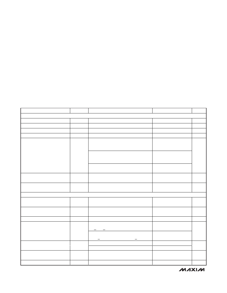
MAX13362
24-Channel Automotive Switch Monitor
2
_______________________________________________________________________________________
ABSOLUTE MAXIMUM RATING
ELECTRICAL CHARACTERISTICS
(V
DD
= 5V, V
VS
= 14V, T
A
= -40°C to +125°C, unless otherwise noted. Typical values are at T
A
=+25°C.)
Stresses beyond those listed under “Absolute Maximum Ratings” may cause permanent damage to the device. These are stress ratings only, and functional
operation of the device at these or any other conditions beyond those indicated in the operational sections of the specifications is not implied. Exposure to
absolute maximum rating conditions for extended periods may affect device reliability.
V
DD
, CLK, SDI,
CS to GND ......................................-0.3V to +6V
VS,
SD, INT to GND................................................-0.3V to +40V
IN0–IN23 to GND.....................................................-15V to +27V
SDO to GND ...............................................-0.3V to (V
DD
+ 0.3V)
ESD Protection, All Pins (HBM)............................................±2kV
ESD Protection on Pins IN0–IN23 to IEC61000-4-2 Specification
(with added 0.047µF capacitor, and/or 100Ω resistor)....±8kV
Current Into Any Pin..........................................................±20mA
Continuous Power Dissipation (T
A
= +70°C)
(derate 37mW/°C above +70°C)(multilayer board)....2963mW
Operating Temperature Range .........................-40°C to +125°C
Junction Temperature........................................-40°C to +150°C
Storage Temperature Range .............................-65°C to +150°C
Lead Temperature (soldering, 10s) .................................+300°C
PARAMETER
SYMBOL
CONDITIONS
MIN
TYP
MAX
UNITS
POWER SUPPLY
V
DD
Operating Supply Range
V
DD
3
5.5
V
V
DD
Supply Current
I
DD
0.1
10
µA
VS Supply Range
V
VS
(Note 1)
5.5
28
V
VS Undervoltage Lockout
V
UVLO
3
5.5
V
t
POLL
= 64ms, t
POLL_ACT
= 1ms;
LP bit in
internal register = 0, 24 channels active, all
switches open, T
A
= +25°C
100
170
t
POLL
= 64ms, t
POLL_ACT
= 1ms;
LP bit in
internal register = 0, 24 channels active, all
switches open
100
200
Total Supply Current (Flowing
into VS and V
DD
)
I
SUP
Continuous polling mode, wetting current
set to 5mA
1000
µA
VS Supply Current in Shutdown
Mode
I
SDVS
V
SD
= 0, V
VS
= 14V, all switches open, T
A
=
+25°C
6
10
µA
V
DD
Supply Current in Shutdown
Mode
I
SDVDD
V
SD
= 0, V
VS
= 14V, T
A
= +25°C
0.1
5
µA
SWITCH INPUTS
Input Voltage Threshold
V
TH
V
VS
= 5.5V to 28V, measured with 100
Ω
series resistor for high-side switches
2.5
3.7
V
Input Hysteresis
V
H
V
VS
= 5.5V to 28V, measured with 100
Ω
series resistor for high-side switches
0.2
V
Wetting Current Rise/Fall Time
t
IWETT
5
µs
Wetting current set to 15mA,
9V
<
V
VS
<
18V
12.7
15
17.25
Wetting Current
I
WETT
Wetting current set to 15mA,
(5.5V
<
V
VS
< 9V) or (18V < V
VS
<
28V)
10.5
15
19.5
mA
V
IN_
= 0, T
A
= +25°C
2
IN0–IN23 Input Current
I
IN_
V
IN_
= 14V, T
A
= +25°C (Note 2)
16
30
µA
IN0–IN23 Input Leakage Current
in Shutdown
I
LEAKSD
V
VS
= 0 or 14V, V
SD
= 0, T
A
= +25°C
±2
µA
IN4–IN23 Dropout Voltage
V
DO15
I
WETT
= 15mA (Note 3)
2.8
4.0
V