Table 3. polling time setting, Table 2. command register map, Table 4. polling-active time setting – Rainbow Electronics MAX13362 User Manual
Page 11: Command register, Lh_: switch configuration for in0–in3 and in23, P0–p3: polling time, Pa0–pa2: polling active time
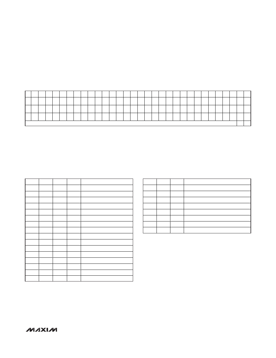
Command Register
Three 32-bit command registers are used to configure
the MAX13362 for various modes of operation and are
accessed by the SPI-compatible interface (see Table 2).
LH_: Switch Configuration for IN0–IN3 and IN23
The LH0–LH3 and LH23 bits set the switch configuration
for IN0–IN3 and IN23, respectively. Set LH_ to 0 to con-
figure the input channel to ground connected. Set LH_
to1 to configure the input channel to battery connected.
The default configuration after power-on is LH_ = 0,
ground connected.
P0–P3: Polling Time
P0–P3 are used to set the polling time as shown in Table 3.
PA0–PA2: Polling Active Time
PA0–PA2 are used to set the polling active time as
shown in Table 4.
MAX13362
24-Channel Automotive Switch Monitor
______________________________________________________________________________________
11
P3
P2
P1
P0
POLLING TIME (ms)
0
0
0
0
Continuous*
0
0
0
1
4.096
0
0
1
0
4.096
0
0
1
1
4.096
0
1
0
0
4.096
0
1
0
1
4.096
0
1
1
0
8.192
0
1
1
1
16.384
1
0
0
0
32.768
1
0
0
1
65.536
1
0
1
0
131
1
0
1
1
262.1
1
1
0
0
524.3
1
1
0
1
1049
1
1
1
0
2097
1
1
1
1
4194
Table 3. Polling Time Setting
D29 D28 D27
D26 D25 D24 D23 D22 D21 D20 D19
D18 D17 D16
D15
D14 D13 D12 D11
D10
D9
D8
D7
D6
D5
D4
D3
D2
D1
D0
CB1 CB0
X
LP
PA2
PA1 PA0
W23.
0
W22.
0
W21
.0
W20
.0
W19
.0
W18
.0
W17
.0
W16.
0
W15
.0
W14
.0
W13
.0
W12
.0
W11
.0
W10
.0
W9.
0
W8.
0
W7.
0
W6.
0
W5.
0
W4.
0
W3.
0
W2.
0
W1.
0
W0.
0
X
0
0
X
P3
P2
P1
P0
W23.
1
W22.
1
W21
.1
W20
.1
W19
.1
W18
.1
W17
.1
W16.
1
W15
.1
W14
.1
W13
.1
W12
.1
W11
.1
W10
.1
W9.
1
W8.
1
W7.
1
W6.
1
W5.
1
W4.
1
W3.
1
W2.
1
W1.
1
W0.
1
X
0
1
LH2
3
LH3 LH2
LH1 LH0 IE23 IE22 IE21 IE20 IE19 IE18 IE17 IE16 IE15 IE14 IE13 IE12 IE11 IE10
IE9
IE8
IE7
IE6
IE5
IE4
IE3
IE2
IE1
IE0
X
1
0
NO OPERATION (NO DATA WRITTEN)
1
1
Table 2. Command Register Map
*
Default POR Value.
*
Default POR value.
Table 4. Polling-Active Time Setting
PA2
PA1
PA0
POLLING ACTIVE TIME (µs)
0
0
0
64
0
0
1
128
0
1
0
256
0
1
1
512*
1
0
0
1024
1
0
1
2048
1
1
0
4096
1
1
1
4096