Channel automotive switch monitor, Table 1. bit description – Rainbow Electronics MAX13362 User Manual
Page 10
MAX13362
Serial Peripheral Interface
(
CS, SDO, SDI, CLK)
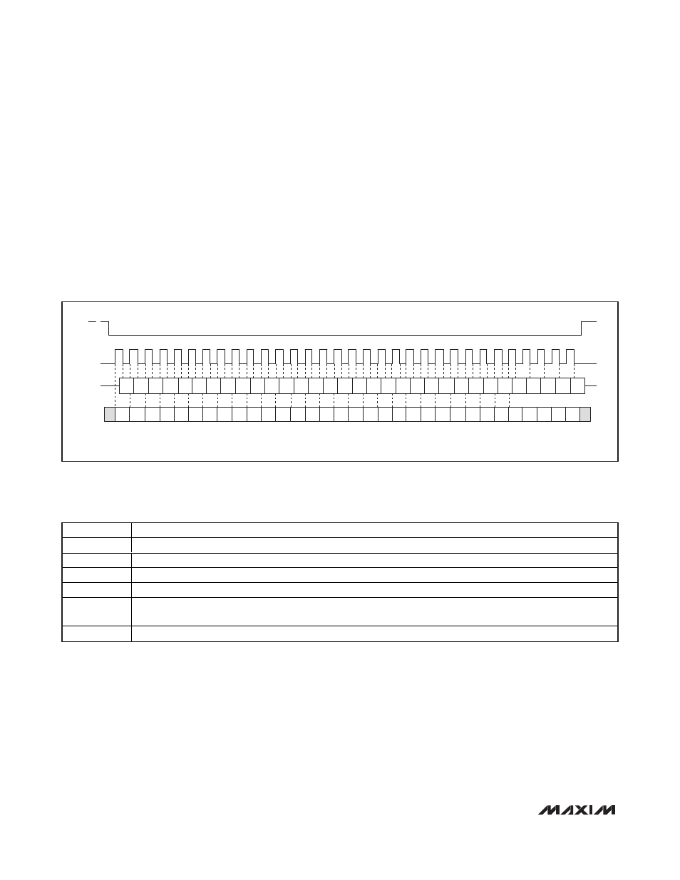
The MAX13362 operates as a serial peripheral interface
(SPI) slave device. An SPI master accesses and pro-
grams the MAX13362 by reading/writing the control
registers. The control registers are 32 bits wide, have 2
command bits (or register addresses) and 30 data bits
(see Table 1). Figure 3 shows the read/write sequence
through SPI. The SPI logic counts the number of bits
clocked into the IC (using a modulo-32 counter so that
daisy chaining is possible) and enables data latching
only if exactly 32 bits (or an integer multiple thereof)
have been clocked in.
Status Register
The status register contains the status of the switches
connected to IN0–IN23. The status register also con-
tains an overtemperature warning bit, a power-on-reset
bit and a device type bit (see Table 1). The status reg-
ister is accessed by the SPI-compatible interface.
24-Channel Automotive Switch Monitor
10
______________________________________________________________________________________
Figure 3. SPI Read/Write Sequence
CS
CLK
SDI
SDO
D12
CB0 CB1 D0
RST
DT
Z
D1 D2 D3 D4 D5 D6 D7 D8 D9 D10 D11
T
S0
S8
S7
S6
S5
S4
S3
S2
S1
S9 S10
D24
D13 D14 D15 D16 D17 D18 D19 D20 D21 D22 D23
D29
D25 D26 D27 D28
Z
S11 S12 S13 S14 S15 S16 S17 S18 S19 S20 S21 S22 S23
x
x
x
x
x
NOTE: X = UNUSED, Z = HIGH IMPEDANCE.
BIT NAME
BIT DESCRIPTION
CB0, CB1
Command bits. Select the internal register to which data bits D0–D29 are to be written.
D0–D29
Data bits.
S0–S23
Switch state bit. 0 = switch open, 1 = switch closed.
T
Overtemperature bit. When overtemperature occurs, this bit is set to 1. It is reset on the rising edge of
CS.
RST
Power-on-reset bit. It indicates whether the IC has had a power-on-reset since the last SPI read. 0 = device has
been reset. RST is set to 1 on the rising edge of
CS.
DT
Device type. 0 = reserved for future use, 1 = MAX13362.
Table 1. Bit Description