Channel automotive switch monitor, Table 5. wetting current setting – Rainbow Electronics MAX13362 User Manual
Page 12
MAX13362
IE_: Interrupt Enable
The IE_ bit programs the switch input channel, IN_, to
be interrupt-enabled or interrupt-disabled (0 = interrupt
disabled, 1 = interrupt enabled). The default value after
power-on is 0.
W_.0 and W_.1: Wetting Current
W_.0 and W_.1 bits set the corresponding switch
channel-wetting current as shown in Table 5.
LP: Low Quiescent Current Bit
In polling mode, when
LP is set to 0, the IC is operating
with the lowest quiescent current. The channels that are
not enabled to interrupt have their wetting current dis-
abled and are not monitored. The first pulse of wetting
current after the switch is closed and sampled is 5mA
unless the wetting current for that channel is set to
0mA. The default value of
LP after power-on is 0. When
LP is 1, all channels are monitored and the wetting cur-
rent for each channel is set to the value determined by
W_.0 and W_.1. If the MAX13362 is in continuous
mode,
LP is ignored.
Operating Modes
The MAX13362 features three modes of operation: con-
tinuous mode, polling mode, and shutdown mode. In
continuous mode, the wetting currents (if enabled) are
continuously applied to the closed switches. In polling
mode, the wetting currents are applied to the closed
switches for a preset duration to reduce the power con-
sumption. In shutdown mode, all switch inputs are high
impedance and all circuitry is shutdown.
Continuous Mode Operation (P0–P3 = 0)
In continuous mode, reading of the switch status is initi-
ated by a falling edge on
CS. The microcontroller initi-
ates a low pulse on
CS to update the MAX13362 switch
status register. If
INT remains high, no action needs be
taken by the microcontroller. If
INT goes low, the micro-
controller may perform a read operation to read the
updated switch status. On the rising edge of
CS, INT is
updated. To get correct data, the microcontroller must
wait 10µs before initiating a switch status read opera-
tion. (See Figure 4.)
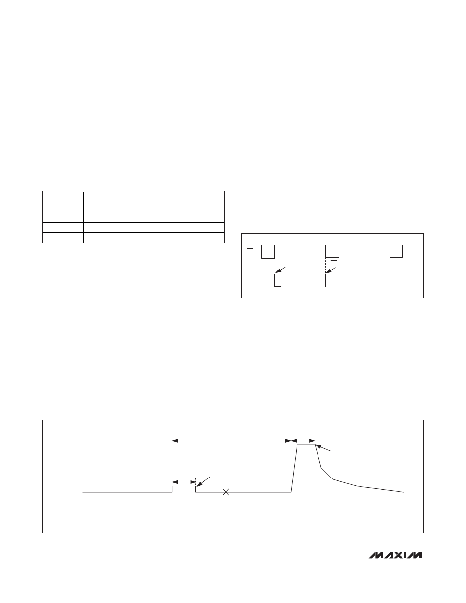
Polling-Mode Operation
In polling mode (see Figure 5), each switch input is
sampled for a programmable polling active time set by
the PA0–PA2 bits between 64µs and 4ms (see Table 4).
Sampling is repeated at a period set by the P0–P3 bits
(from 4ms to continuous, see Table 3). All switch inputs
are sampled simultaneously at the end of the polling
active time. Wetting currents (if enabled) are applied to
closed switches during the polling active time.
Therefore, the polling mode reduces the current con-
sumption from the VS power supply to some value
dependent on the polling time chosen.
24-Channel Automotive Switch Monitor
12
______________________________________________________________________________________
*
Default POR value.
Table 5. Wetting Current Setting
W_.1
W_.0
WETTING CURRENT (mA)
0
0
0*
0
1
5
1
0
10
1
1
15
CS
INT
SWITCH
STATUS
CHANGE
INT UPDATED, PERFORM READ OPERATION
Figure 4. Continuous Mode Operation
GROUND-CONNECTED
SWITCH-INPUT
INT
SWITCH OPEN
POLLING TIME
SWITCH
POSITION
SAMPLED
SWITCH
POSITION
SAMPLED
POLLING ACTIVE TIME
POLLING
ACTIVE TIME
Figure 5. Switch Sampling in Polling Mode