Table 1. power-down command bits – Rainbow Electronics MAX5842 User Manual
Page 9
MAX5842
Quad, 12-Bit, Low-Power, 2-Wire, Serial
Voltage-Output DAC
_______________________________________________________________________________________
9
by a START (S) or REPEATED START (S
r
) condition and
a STOP (P) condition. Each word transmitted over the
bus is 8 bits long and is always followed by an
acknowledge clock pulse.
The MAX5842 SDA and SCL drivers are open-drain
outputs, requiring a pullup resistor to generate a logic
high voltage (see Typical Operating Circuit). Series
resistors R
S
are optional. These series resistors protect
the input stages of the MAX5842 from high-voltage
spikes on the bus lines, and minimize crosstalk and
undershoot of the bus signals.
Bit Transfer
One data bit is transferred during each SCL clock
cycle. The data on SDA must remain stable during the
high period of the SCL clock pulse. Changes in SDA
while SCL is high are control signals (see START and
STOP Conditions). Both SDA and SCL idle high when
the I
2
C bus is not busy.
START and STOP Conditions
When the serial interface is inactive, SDA and SCL idle
high. A master device initiates communication by issu-
ing a START condition. A START condition is a high-to-
low transition on SDA with SCL high. A STOP condition
is a low-to-high transition on SDA, while SCL is high
(Figure 2). A START condition from the master signals
the beginning of a transmission to the MAX5842. The
master terminates transmission by issuing a not
acknowledge followed by a STOP condition (see
Acknowledge Bit (ACK)). The STOP condition frees the
bus. If a repeated START condition (Sr) is generated
instead of a STOP condition, the bus remains active.
When a STOP condition or incorrect address is detect-
ed, the MAX5842 internally disconnects SCL from the
serial interface until the next START condition, minimiz-
ing digital noise and feedthrough.
Early STOP Conditions
The MAX5842 recognizes a STOP condition at any
point during transmission except if a STOP condition
occurs in the same high pulse as a START condition
(Figure 3). This condition is not a legal I
2
C format; at
least one clock pulse must separate any START and
STOP conditions.
Repeated START Conditions
A REPEATED START (S
r
) condition may indicate a
change of data direction on the bus. Such a change
occurs when a command word is required to initiate a
read operation. S
r
may also be used when the bus
master is writing to several I
2
C devices and does not
want to relinquish control of the bus. The MAX5842 ser-
ial interface supports continuous write operations with
or without an S
r
condition separating them. Continuous
POWER-DOWN
COMMAND BITS
PD1
PD0
MODE/FUNCTION
0
0
Power-up device. DAC output
restored to previous value.
0
1
Power-down mode 0. Power down
device with output floating.
1
0
Power-down mode 1. Power down
device with output terminated with
1k
Ω to GND.
1
1
Power-down mode 2. Power down
device with output terminated with
100k
Ω to GND.
Table 1. Power-Down Command Bits
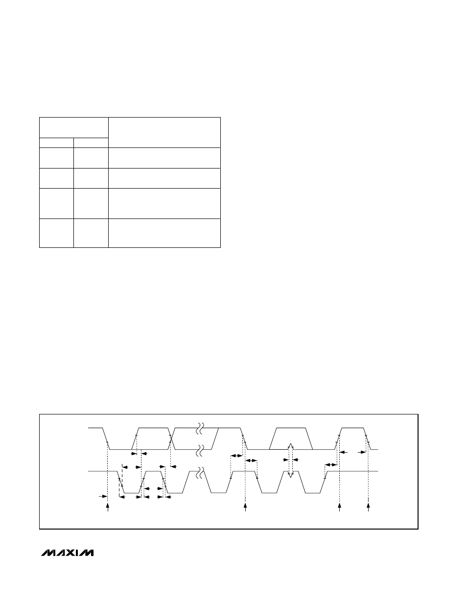
SCL
SDA
STOP
CONDITION
START
CONDITION
REPEATED START CONDITION
START CONDITION
t
LOW
t
SU, DAT
t
SU, STA
t
SP
t
BUF
t
HD, STA
t
SU, STO
t
R
t
F
t
HD, STA
t
HIGH
t
HD, DAT
Figure 1. 2-Wire Serial Interface Timing Diagram