Table 3. command byte definitions (continued) – Rainbow Electronics MAX5842 User Manual
Page 13
MAX5842
Quad, 12-Bit, Low-Power, 2-Wire, Serial
Voltage-Output DAC
______________________________________________________________________________________
13
SERIAL DATA INPUT
C3
C2
C1
C0
D11
D10
D9
D8
FUNCTION
1
1
1
0
X
X
X
X
Update all DAC outputs simultaneously. Device ignores
D11-D8. Do not send the data byte.
1
1
1
1
0
0
0
0
E xtend ed com m and m od e. The next w or d w r i tes to the p ow er -
d ow n r eg i ster s ( E xtend ed C om m and M od e) .
1
1
1
1
0
0
0
1
Read DAC A data. The device expects an S
r
condition
followed by an address word with R/W = 1.
1
1
1
1
0
0
1
0
Read DAC B data. The device expects an S
r
condition
followed by an address word with R/W = 1.
1
1
1
1
0
1
0
0
Read DAC C data. The device expects an S
r
condition
followed by an address word with R/W = 1.
1
1
1
1
1
0
0
0
Read DAC D data. The device expects an S
r
condition
followed by an address word with R/W = 1.
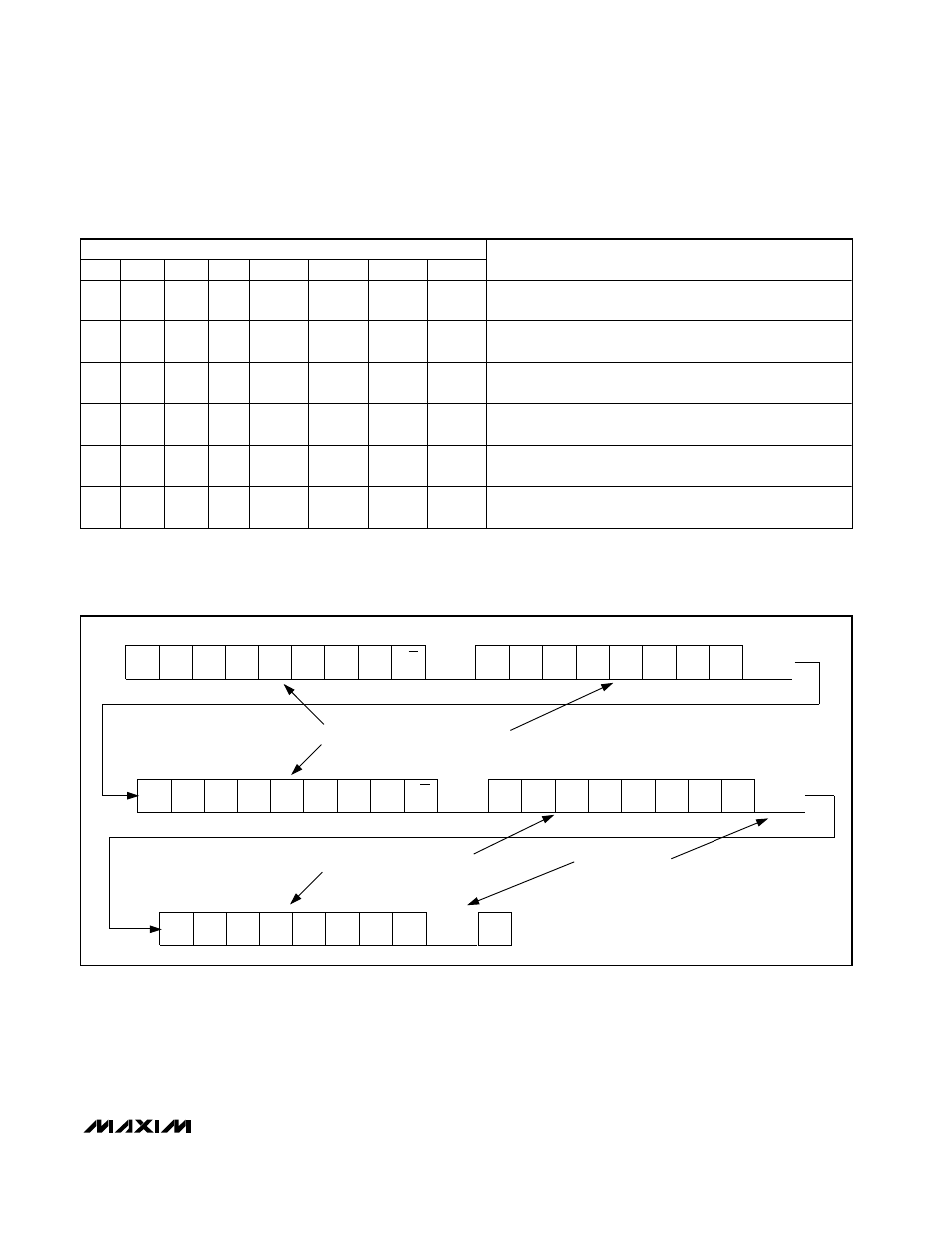
Table 3. Command Byte Definitions (continued)
S
A6
A5
A4
A3
A2
A1
A0
C3
C2
C1
C0
D11
D10
D9
D8
Sr
A6
A5
A4
A3
A2
A1
A0
MSB
LSB
MSB
LSB
LSB
MSB
ACK
ACK
ACK
D7
D6
D5
D4
D3
D2
D1
D0
MSB
LSB
ACK
ACK
P
R/W
= 1
X
X
PD1
PD0
D11
D10
D9
D8
MSB
LSB
DATA BYTES GENERATED BY MASTER DEVICE
DATA BYTES GENERATED BY MAX5842
ACK GENERATED BY
MASTER DEVICE
R/W
= 0
Figure 8. Example Read Word Data Sequence