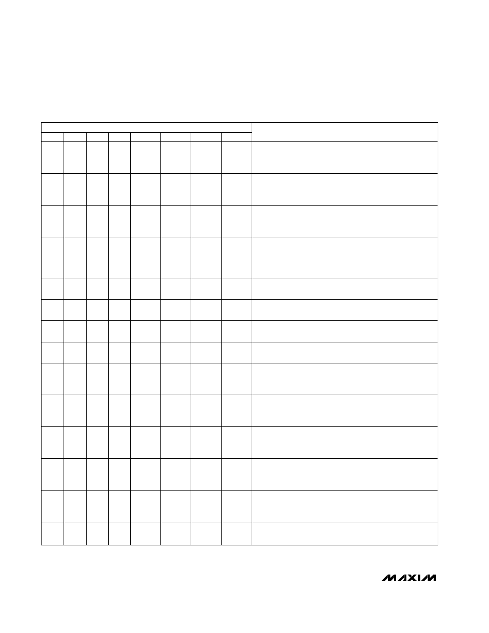
Table 3. command byte definitions – Rainbow Electronics MAX5842 User Manual
Page 12
MAX5842
Quad, 12-Bit, Low-Power, 2-Wire, Serial
Voltage-Output DAC
12
______________________________________________________________________________________
SERIAL DATA INPUT
C3
C2
C1
C0
D11
D10
D9
D8
FUNCTION
0
0
0
0
DAC
DATA
DAC
DATA
DAC
DATA
DAC
DATA
Load DAC A input and DAC registers with new data.
Contents of DAC B, C, and D input registers are transferred
to the respective DAC registers. All outputs are updated.
0
0
0
1
DAC
DATA
DAC
DATA
DAC
DATA
DAC
DATA
Load DAC B input and DAC registers with new data.
Contents of DAC A, C, and D input registers are transferred
to the respective DAC registers. All outputs are updated.
0
0
1
0
DAC
DATA
DAC
DATA
DAC
DATA
DAC
DATA
Load DAC C input and DAC registers with new data.
Contents of DAC A, B, and D input registers are transferred
to the respective DAC registers. All outputs are updated.
0
0
1
1
DAC
DATA
DAC
DATA
DAC
DATA
DAC
DATA
Load DAC D input and DAC registers with new data.
Contents of DAC A, B, and C input registers are transferred
to the respective DAC registers. All outputs are updated
simultaneously.
0
1
0
0
DAC
DATA
DAC
DATA
DAC
DATA
DAC
DATA
Load DAC A input register with new data. DAC outputs
remain unchanged.
0
1
0
1
DAC
DATA
DAC
DATA
DAC
DATA
DAC
DATA
Load DAC B input register with new data. DAC outputs
remain unchanged.
0
1
1
0
DAC
DATA
DAC
DATA
DAC
DATA
DAC
DATA
Load DAC C input register with new data. DAC outputs
remain unchanged.
0
1
1
1
DAC
DATA
DAC
DATA
DAC
DATA
DAC
DATA
Load DAC D input register with new data. DAC outputs
remain unchanged.
1
0
0
0
DAC
DATA
DAC
DATA
DAC
DATA
DAC
DATA
Data in all input registers is transferred to respective DAC
registers. All DAC outputs are updated simultaneously. New
data is loaded into DAC A input register.
1
0
0
1
DAC
DATA
DAC
DATA
DAC
DATA
DAC
DATA
Data in all input registers is transferred to respective DAC
registers. All DAC outputs are updated simultaneously. New
data is loaded into DAC B input register.
1
0
1
0
DAC
DATA
DAC
DATA
DAC
DATA
DAC
DATA
Data in all input registers is transferred to respective DAC
registers. All DAC outputs are updated simultaneously. New
data is loaded into DAC C input register.
1
0
1
1
DAC
DATA
DAC
DATA
DAC
DATA
DAC
DATA
Data in all input registers is transferred to respective DAC
registers. All DAC outputs are updated simultaneously. New
data is loaded into DAC D input register.
1
1
0
0
DAC
DATA
DAC
DATA
DAC
DATA
DAC
DATA
Load all DACs with new data and update all DAC outputs
simultaneously. Both input and DAC registers are updated
with new data.
1
1
0
1
DAC
DATA
DAC
DATA
DAC
DATA
DAC
DATA
Load all input registers with new data. DAC outputs remain
unchanged.
Table 3. Command Byte Definitions