C-compatible interface, Table 2. command-byte assignments, Table 3. fan speed – Rainbow Electronics MAX6651 User Manual
Page 9
MAX6650/MAX6651
Fan-Speed Regulators and Monitors
with SMBus/I
2
C-Compatible Interface
_______________________________________________________________________________________
9
tor that overrides the internal oscillator (see General-
Purpose Input/Output). When using an external oscillator
(f
OSC
), calculate the Fan-Speed Register value with f
CLK
equal to f
OSC
. Codes above F8h (1111 1000) are
allowed, but will not significantly decrease the frequency.
Configuration-Byte Register
The Configuration-Byte Register (Table 4) adjusts the
prescaler, changes the tachometer threshold voltage,
and sets the mode of operation. The three least-signifi-
cant bits configure the prescaler division used to scale
the tachometer period. Select the prescaler value so the
fan’s full speed is achieved with a register value of
approximately 64 (0100 0000) to optimize speed range
and resolution (see the Fan Speed Register section). The
fourth bit selects the fan operating voltage.
The fifth and sixth bits configure the operating mode.
The MAX6650/MAX6651 have four modes of operation:
full-on, full-off (shutdown), closed-loop, and open-loop.
In closed-loop operation, the external microcontroller
(µC) sets the desired speed by writing an 8-bit word to
the Fan-Speed Register (see the Fan-Speed Register
section). The MAX6650/MAX6651 monitor the fan’s
tachometer output and automatically adjust the voltage
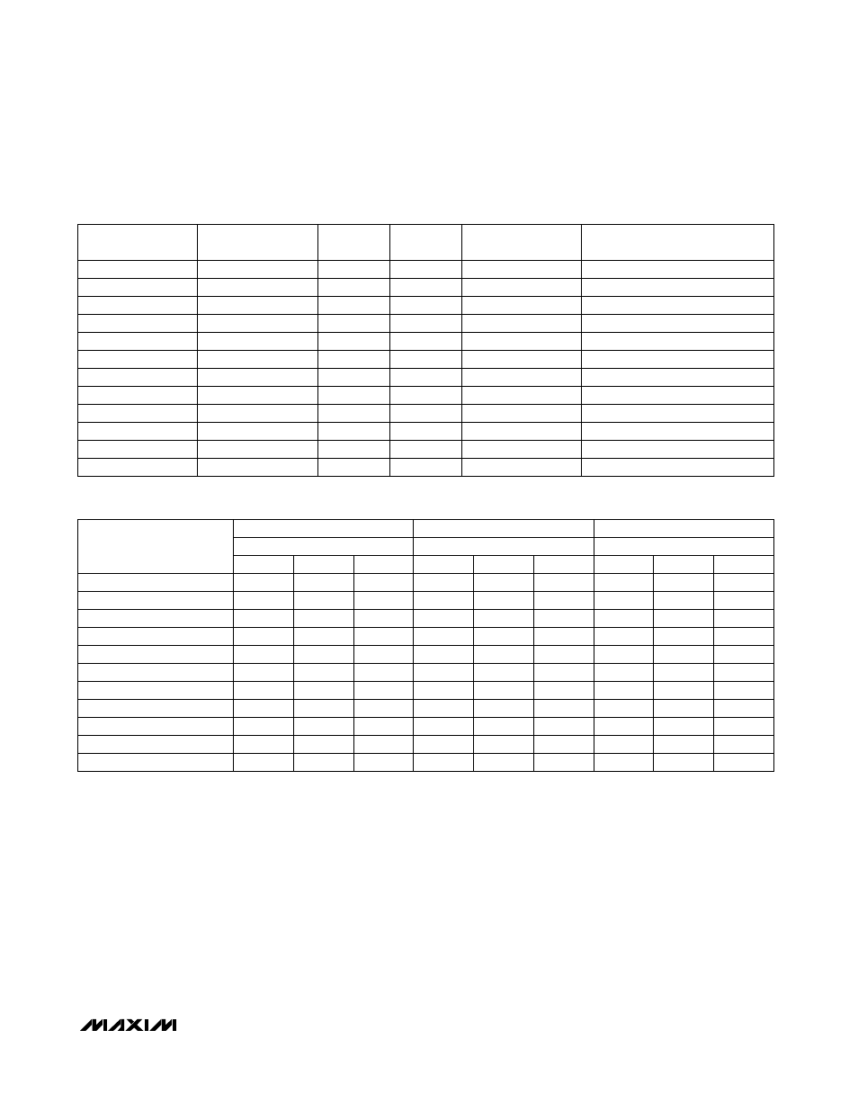
Table 2. Command-Byte Assignments
COUNT
x
SPEED
0000 0000
x
CONFIG
0000 0010
x
READ
GPIO DEF
0000 0100
0001 0110
x
x
x
x
WRITE
x
02h
Tachometer count time
FFh
0Ah
00h
POR (DEFAULT)
STATE
COMMAND
GPIO definition
REGISTER
Configuration
Fan speed
FUNCTION
DAC
0000 0110
x
x
00h
DAC
ALARM ENABLE
0000 1000
x
x
00h
Alarm enable
ALARM
0000 1010
x
—
00h
Alarm status
TACH0
0000 1100
x
—
00h
Tachometer 0 count
TACH1
0000 1110
x
—
00h
Tachometer 1 count
TACH2
0001 0000
x
—
00h
Tachometer 2 count
TACH3
0001 0010
x
—
00h
Tachometer 3 count
GPIO STAT
0001 0100
x
—
h1Fh
GPIO status
Table 3. Fan Speed
*
0000 0000
1.0
*
0000 0001
1.0
*
0000 0010
1.5
K
SCALE
(ms)
*
*
*
t
TACH
K
SCALE
330
500
500
*
*
*
K
TACH
*
*
*
FAN SPEED (RPS)
—
*
500
480
—
240
—
—
—
—
—
—
—
0001 1110
16
3.9
*
32
128
64
0001 1111
16
4.0
1.0
31
124
0010 0000
17
4.2
20,000
1.0
30
120
30,000
—
—
—
—
—
—
30,000
0100 0000
33
8.2
2.1
15.3
61.1
—
—
—
—
—
—
—
1111 1000
125
31
7.8
4
15.9
1900
1900
1800
—
910
—
240
K
SCALE
*
*
*
—
7700
7400
7200
—
3700
—
960
*
*
*
FAN SPEED (RPM)
—
*
30,000
29,000
—
15,000
—
3830
4
16
1
1
4
16
1
4
16
*The minimum allowed tachometer period is 1ms.