C-compatible interface, Detailed description, Pin description – Rainbow Electronics MAX6651 User Manual
Page 5
MAX6650/MAX6651
Fan-Speed Regulators and Monitors
with SMBus/I
2
C-Compatible Interface
_______________________________________________________________________________________
5
Detailed Description
The MAX6650/MAX6651 use an SMBus/I
2
C-Compatible
interface to regulate and monitor the speed of
5VDC/12VDC brush-less fans with built-in open-collec-
tor/drain tachometers. Regulating fan speed propor-
tionally with temperature saves power, increases fan
life, and reduces acoustic noise. Since fan speed is
proportional to the voltage across the fan, the
MAX6650/MAX6651 control the speed by regulating the
voltage on the low side of the fan with an external MOS-
FET or bipolar transistor.
The MAX6650/MAX6651 each contain two internal con-
trol loops. The first loop controls the voltage across the
fan. The internal digital-to-analog converter (DAC) sets
the reference voltage for an internal amplifier (Figure 1),
which then drives the gate of an external N-channel
MOSFET (or the base of a bipolar transistor) to regulate
the voltage on the low side of the fan. As the reference
voltage provided by the DAC changes, the feedback
amplifier automatically adjusts the feedback voltage,
which changes the voltage across the fan.
The second control loop consists of the internal digital
logic that controls the fan’s speed. The MAX6650/
MAX6651 control fan speed by forcing the tachometer
frequency to equal a reference frequency set by the
Fan-Speed Register, the prescaler, and the internal
oscillator (see the Fan-Speed Register section). When
the tachometer frequency is too high, the value of the
DAC’s input register is increased by the regulator.
Once the DAC voltage increases, the analog control
loop forces the feedback voltage to rise, which reduces
the voltage across the fan. Since fan speed is propor-
tional to the voltage across the fan, the fan slows down.
2-Wire SMBus/I
2
C-Compatible
Digital Interface
From a software perspective, the MAX6650/MAX6651
appear as a set of byte-wide registers that contain
speed control, tachometer count, alarm conditions, or
configuration bits. These devices use a standard
SMBus/I
2
C-compatible 2-wire serial interface to access
the internal registers.
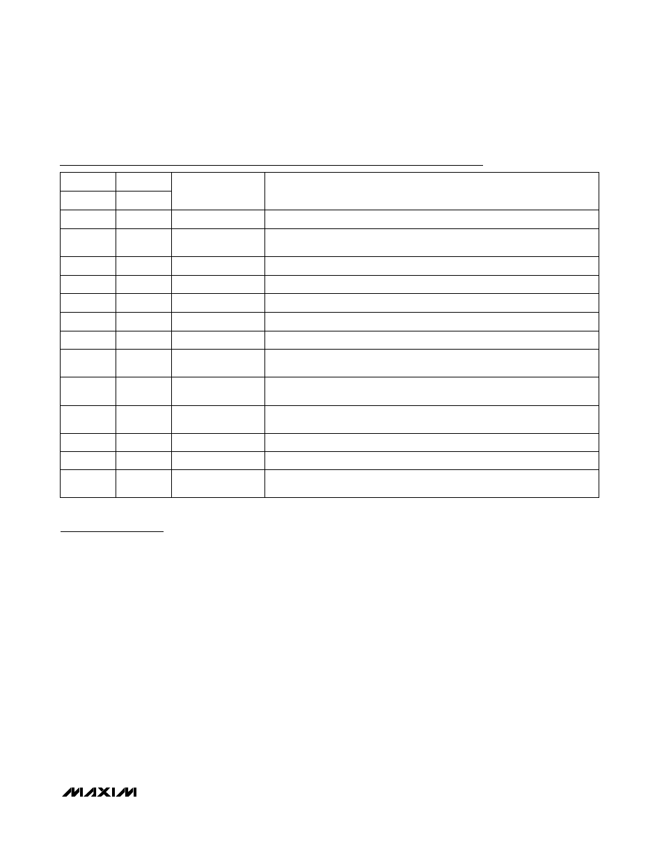
Pin Description
FUNCTION
NAME
PIN
PIN
MAX6650
MAX6651
Tachometer Input. Used to close the loop around the tachometer.
TACH0
1
1
—
2, 3, 16
TACH2, TACH3,
TACH1
Tachometer Inputs. Used to monitor tachometers only.
Ground
GND
4
2
3
5
SDA
2-Wire Serial-Data Input/Output (open drain)
2-Wire Serial Clock Input
SCL
6
4
5
8
ADD
Slave Address Select Input (Table 1)
General-Purpose Input/Output (open drain). Configurable to act either as an out-
put or as an input (
FULL ON or general purpose).
General-Purpose Input/Output (open drain). Configurable to act as a general
input/output line or an active-low
ALERT output.
General-Purpose Input/Output (open drain). Configurable to act as a general
input/output line, an internal clock output, or an external clock input.
Output. Drives the external MOSFET or bipolar transistor.
+3.0V to +5.5V Power Supply
Feedback Input. Closes the loop around the external MOSFET or bipolar tran-
sistor.
FB
V
CC
OUT
GPIO2
GPIO0
GPIO1
9
6
7
10
11
—
13
8
9
14
15
10
—
7, 12
GPIO4, GPIO3
General-Purpose Input/Output (open drain)