C-compatible interface, Table 4. configuration byte register – Rainbow Electronics MAX6651 User Manual
Page 10
across the fan until the desired speed is reached. Open-
loop operation allows the µC to regulate fan speed direct-
ly. The µC reads the fan speed from the Tach-
ometer-Count Register. Based on the tachometer
count, the µC decides if the fan speed requires adjust-
ment, and changes the voltage across the fan by writ-
ing an 8-bit word to the DAC Register. Full-on mode
applies the maximum voltage across the fan, forcing it
to spin at full speed. Configuring GPIO1 (see the
General-Purpose Input/Output section) as an active-low
input provides additional hardware control that fully
turns on the fan and overrides all software commands.
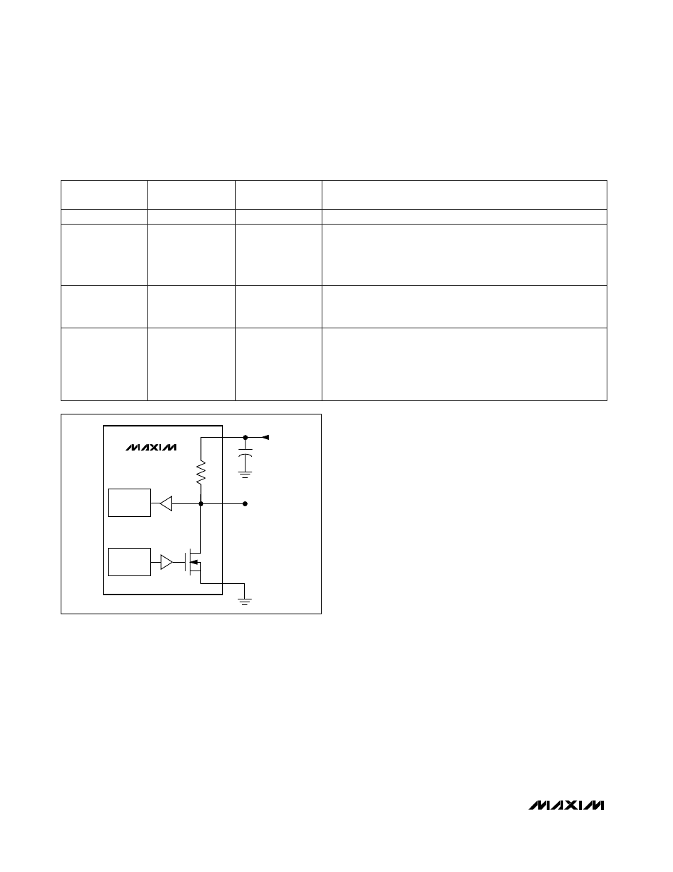
General-Purpose Input/Output
The GPIO pins connect to the drain of the internal N-
channel MOSFET and pullup resistor (
Figure 5
). When
the N-channel MOSFET is off (Table 5), the pullup resis-
tor provides a logic-level high output. However, with the
MOSFET off, the GPIO may serve as an input pin and
its state is read from the GPIO Status Register (Table
6). The MAX6650/MAX6651 power up with the MOSFET
off, so input signals may be safely connected to the
GPIO pins. When using the GPIO pin as a general-pur-
pose output, change the output by writing to the GPIO
Definition Register.
GPIO0 may be configured as an
ALERT output that will
go low whenever a fault-condition is detected (see the
Alarm-Enable and Status Registers section). GPIO1
may be configured as a
FULL ON input to allow hard-
ware control to fully turn on the fan in case of software
or µC failure. GPIO2 (MAX6651 only) may be config-
ured as an internal clock output or as an external clock
input to allow synchronization of multiple devices.
Alarm-Enable and Status Registers
The alarms are enabled only when the appropriate bits of
the Alarm-Enable Register are set (Table 7). The maxi-
mum and minimum output level alarms function only
when the device is configured to operate in the closed-
loop mode (see the Configuration-Byte Register section).
The Alarm Status Register allows the system to deter-
mine which alarm caused the alert output (Table 8).
The set-alarm and alert outputs clear after reading the
MAX6650/MAX6651
Fan-Speed Regulators and Monitors
with SMBus/I
2
C-Compatible Interface
10
______________________________________________________________________________________
Table 4. Configuration Byte Register
5/12V
BIT
MODE
5 to 4
NAME
3
1
00
POR (DEFAULT)
STATE
Fan/Tachometer Voltage:
0 = 5V
1 = 12V (default)
Operating Mode:
00 = Software full-on (default)
01 = Software off (shutdown)
10 = Closed-loop operation
11 = Open-loop operation
FUNCTION
2 to 0 (LSB)
SCALE
010
Prescaler Division:
000 = Divide by 1
001 = Divide by 2
010 = Divide by 4 (default)
011 = Divide by 8
100 = Divide by 16
7 (MSB) to 6
—
0
Always 0
Figure 5. General-Purpose Input/Output Structure
MAX6650
MAX6651
100k
GPIO
STATUS
REGISTER
V
CC
3.0V TO 5.5V
V
CC
C
BYPASS
GPIO_
GND
GPIO
DEFINITION
REGISTER