C-compatible interface, Command-byte functions, Fan-speed register – Rainbow Electronics MAX6651 User Manual
Page 8
MAX6650/MAX6651
Fan-Speed Regulators and Monitors
with SMBus/I
2
C-Compatible Interface
8
_______________________________________________________________________________________
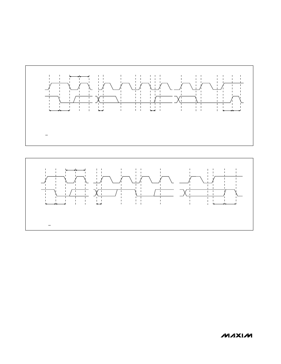
SMBCLK
A
B
C
D
E
F
G
H
I
J
K
SMBDATA
t
SU:STA
t
HD:STA
t
LOW
t
HIGH
t
SU:DAT
t
HD:DAT
t
SU:STO
t
BUF
A = START CONDITION
B = MSB OF ADDRESS CLOCKED INTO SLAVE
C = LSB OF ADDRESS CLOCKED INTO SLAVE
D = R/W BIT CLOCKED INTO SLAVE
E = SLAVE PULLS SMBDATA LINE LOW
L
M
F = ACKNOWLEDGE BIT CLOCKED INTO MASTER
G = MSB OF DATA CLOCKED INTO SLAVE
H = LSB OF DATA CLOCKED INTO SLAVE
I = SLAVE PULLS SMBDATA LINE LOW
J = ACKNOWLEDGE CLOCKED INTO MASTER
K = ACKNOWLEDGE CLOCK PULSE
L = STOP CONDITION, DATA EXECUTED BY SLAVE
M = NEW START CONDITION
SMBCLK
A = START CONDITION
B = MSB OF ADDRESS CLOCKED INTO SLAVE
C = LSB OF ADDRESS CLOCKED INTO SLAVE
D = R/W BIT CLOCKED INTO SLAVE
A
B
C
D
E
F
G
H
I
J
SMBDATA
t
SU:STA
t
HD:STA
t
LOW
t
HIGH
t
SU:DAT
t
SU:STO
t
BUF
K
E = SLAVE PULLS SMBDATA LINE LOW
F = ACKNOWLEDGE BIT CLOCKED INTO MASTER
G = MSB OF DATA CLOCKED INTO MASTER
H = LSB OF DATA CLOCKED INTO MASTER
I = ACKNOWLEDGE CLOCK PULSE
J = STOP CONDITION
K = NEW START CONDITION
Figure 3. SMBus Write Timing Diagram
Figure 4. SMBus Read Timing Diagram
Command-Byte Functions
The 8-bit Command-Byte Register (Table 2) is the mas-
ter index that points to the various other registers within
MAX6650/MAX6651. The register’s power-on reset
(POR) state is 0000 0000, so that a receive-byte trans-
mission (a protocol that lacks the command byte)
occurring immediately after POR returns the current
speed setting.
Fan-Speed Register
In closed-loop mode, the MAX6650/MAX6651 use the
Fan-Speed Register to set the period of the tachometer
signal that controls the fan speed. The Fan-Speed
Register is ignored in all other modes of operation. The
MAX6650/MAX6651 regulate the fan speed by forcing
the tachometer period (t
TACH
) equal to the scaled reg-
ister value. One revolution of the fan generates two
tachometer pulses, so the required Fan-Speed Register
value (K
TACH)
may be calculated as:
t
TACH
= 1 / (2 x Fan Speed)
K
TACH
= [t
TACH
x K
SCALE
x (f
CLK
/ 128)] - 1
where the fan speed is in rotations per second (RPS),
t
TACH
is the period of the tachometer signal, f
CLK
is the
internal oscillator frequency (254kHz ±10%), and
K
SCALE
is the prescaler value (see Configuration-Byte
Register). Since the fan speed is inversely proportional
to the tachometer period, the Fan-Speed Register value
(K
TACH
) does not linearly control the fan speed (Table
3). Select the prescaler value so the fan’s full speed is
achieved with a register value of approximately 64
(0100 0000) to optimize speed range and resolution.
The MAX6651 may be controlled by an external oscilla-