Rainbow Electronics MAX9512 User Manual
Page 15
MAX9512
Video Filter Amplifier with SmartSleep
and Y/C Mixer Circuit
_
__
__
__
__
__
__
__
__
__
__
__
__
__
__
__
__
__
__
__
__
__
__
__
__
__
__
__
__
__
__
__
__
__
__
__
__
__
__
__
__
__
__
__
__
__
__
__
__
__
__
__
__
__
__
__
__
__
__
__
__
__
__
__
__
__
__
__
__
__
__
__
__
__
__
__
__
__
__
__
__
__
__
__
__
__
_
15
CURRENT
DAC
CURRENT
DAC
VIDEO ENCODER
CHROMA
CIN
YIN
COUT
YOUT
CVBSOUT1
CVBSOUT2
LPF
GND
+3.3V
0.1
µF
V
DD
BUFFER
LOAD SENSE
6dB
75
Ω
220
µF
220
µF
220
µF
220
µF
75
Ω
LPF
BUFFER
LOAD SENSE
6dB
LOAD SENSE
6dB
75
Ω
LOAD SENSE
6dB
75
Ω
MAX9512
LUMA
CVBS1
CVBS2
ACTIVE VIDEO
DETECT
CONTROL
LOGIC
SHDN
SMARTSLEEP
0V
+3.3V
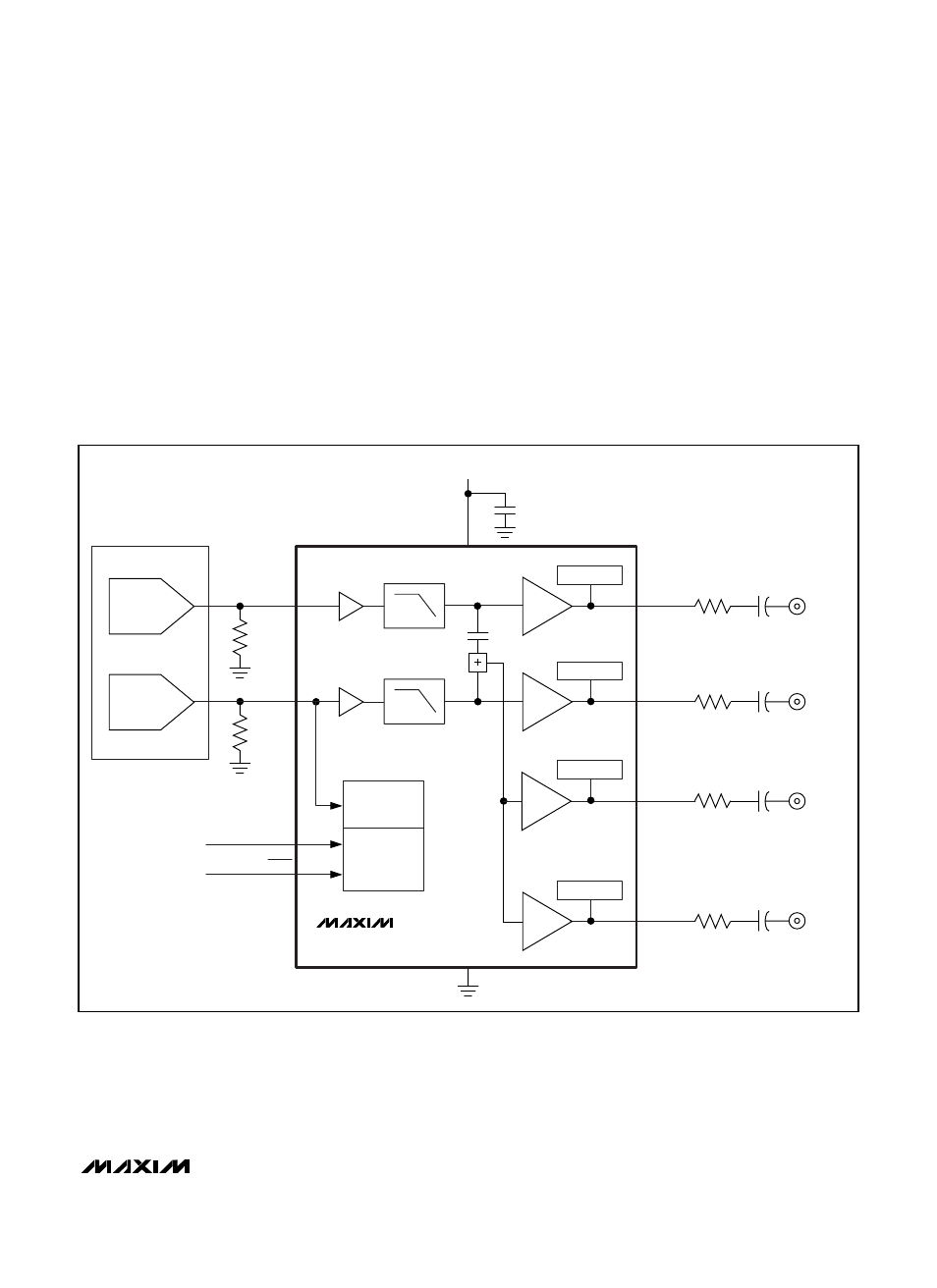
Figure 6. AC-Coupling at the Outputs
AC-Coupling the Outputs
The outputs can be AC-coupled since the output stage
can source and sink current as shown in Figure 6.
Coupling capacitors should be 220µF or greater to
keep the highpass filter formed by the 150Ω equivalent
resistance of the video transmission line to a corner fre-
quency of 4.8Hz or below. The frame rate of PAL sys-
tems is 25Hz, and the frame rate of NTSC systems is
30Hz. The corner frequency should be well below the
frame rate.
Power-Supply Bypassing and Ground
The MAX9512 operates from a single-supply voltage
down to 2.7V, allowing for low-power operation. Bypass
V
DD
to GND with a 0.1µF capacitor. Place all external
components as close to the device as possible.