Electrical characteristics (continued) – Rainbow Electronics MAX8620 User Manual
Page 3
MAX8620Y
µPMIC for Microprocessors or DSPs
in Portable Equipment
_______________________________________________________________________________________
3
PARAMETER
SYMBOL
CONDITIONS
MIN
TYP
MAX
UNITS
OUT1, OUT2 Power-Supply
Rejection Ratio
f = 10Hz to 10kHz, C
OUT_
= 4.7µF,
I
LOAD_
= 30mA
60
dB
f = 100Hz to 100kHz, C
OUT_
= 4.7µF,
I
LOAD_
= 30mA
45
Output Noise Voltage
f = 100Hz to 100kHz, C
OUT_
= 4.7µF,
I
LOAD_
= 30mA, C
BP
open
100
µV
RMS
STEP-DOWN CONVERTER (OUT3)
Output Voltage Range
V
OUT3
0.6
3.3
V
FB Threshold Voltage
V
TH
V
FB
falling
0.6
V
FB Threshold Line Regulation
V
IN1
= V
IN2
= 2.7V to 5.5V (Note 2)
0.08
%/V
T
A
= +25°C
-2
+2
FB Threshold Voltage Accuracy
(Falling) (% of V
TH
)
I
OUT3
= 0mA
T
A
= -40°C to +85°C
-3
+3
%
FB Threshold Voltage Hysteresis
(% of V
TH
)
V
HYS
2
%
OUT3 disabled
10
FB Bias Current
I
FB
V
FB
= 0.5V
10
µA
I
LIM3P
pFET switch
675
950
1200
Current Limit
I
LIM3N
nFET rectifier
875
1000
1200
mA
R
ONP
pFET switch, I
LX
= -200mA
0.65
1.5
On-Resistance
R
ONN
nFET rectifier, I
LX
= +200mA
0.35
0.8
Ω
Rectifier-Off Current Threshold
I
LXOFF
30
60
mA
t
ON
107
Minimum On- and Off-Times
t
OFF
95
ns
OPEN-DRAIN, ACTIVE-LOW RESET OUTPUT (RESET)
RESET Output-Voltage Low
V
OL
I
SINK
= 500µA
0.3
V
RESET Output Leakage Current
V
RESET
= 5.5V
100
nA
RESET Threshold Voltage
V
THR
Percent of the OUT1 regulation voltage
(Note 4)
84
87
90
%
RESET Timeout Period
t
RP
Figure 4
30
60
ms
LDO OUTPUT-VOLTAGE SELECT INPUTS (SEL1, SEL2)
SEL_ Input Low Threshold
1
V
SEL_ Input High Threshold
V
IN_
- 0.2V
V
SEL_ Input Bias Current
V
IN1
= V
IN2
= 4.2V, V
SEL1
= 0V or V
IN1
,
V
SEL2
= 0V or V
IN1
±0.1
µA
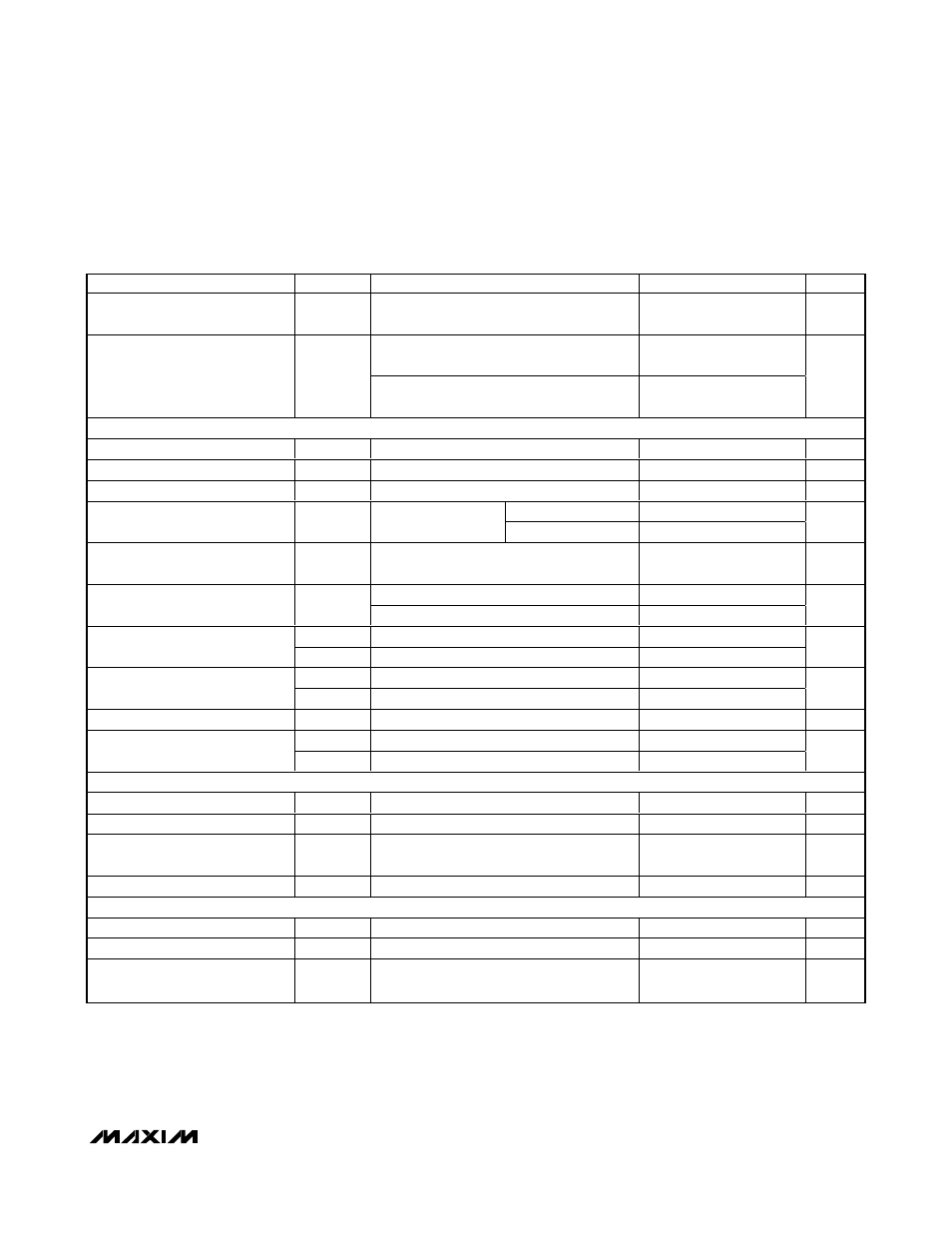
ELECTRICAL CHARACTERISTICS (continued)
(V
IN1
= V
IN2
= +3.7V, C
IN
= 10µF, C
BP
= 0.01µF, T
A
= -40°C to +85°C, unless otherwise noted. Typical values are at T
A
= +25°C.)
(Note 1)
Note 1: Specifications are 100% production tested at T
A
= +25°C. Maximum and minimum limits over temperature are guaranteed
by design and characterization.
Note 2: After startup.
Note 3: Guaranteed by design.
Note 4: RESET asserts low when V
OUT1
drops below the specified percent of the OUT1 regulation voltage.