Max8620y – Rainbow Electronics MAX8620 User Manual
Page 10
MAX8620Y
LDO Output-Voltage
Selection (SEL1, SEL2)
As shown in
Table 1, the LDO output voltages, OUT1
and OUT2, are set according to the logic states of
SEL1 and SEL2. SEL1 and SEL2 are trilevel inputs: IN1,
open, and GND. The input voltage, V
IN1
, must be a
dropout voltage (V
DO
) greater than the selected OUT1
and OUT2 voltages.
Power-Enable Input (PWR_ON)
Drive PWR_ON low to place the MAX8620Y in power-
down mode and reduce supply current to 5.5µA (typ).
Connect PWR_ON to IN1 = IN2 or logic-high to enable
the MAX8620Y. EN2 enables and disables OUT2 when
PWR_ON is high (Table 2). OUT1, OUT2, and OUT3 are
all disabled when PWR_ON is low. HF_PWR can tem-
porarily bring the MAX8620 out of power-down mode
when PWR_ON is low (see the HF_PWR section). In
power-down, the control circuitry, internal-switching p-
channel MOSFET, and the internal synchronous rectifier
(n-channel MOSFET) turn off, and LX becomes high
impedance. In addition, both LDOs are disabled.
OUT2 Enable (
EN2
)
Drive EN2 low to enable OUT2. Drive EN2 high to dis-
able OUT2. If the MAX8620Y is placed into power-
down using PWR_ON (PWR_ON = low), OUT2 does not
power regardless of the status of EN2 (Table 2).
µPMIC for Microprocessors or DSPs
in Portable Equipment
10
______________________________________________________________________________________
ON/OFF
LOGIC
1.25V
REF
87%
REGULATION
P
OUT1
RESET
GND
IN1
LDO THERMAL
SENSOR
MOS DRIVER
WITH I
LIMIT
MOS DRIVER
WITH I
LIMIT
POK
EN2
ERROR-
AMP 2
ERROR-
AMP 1
P
OUT2
PWR_ON
HF_PWR
BP
TIMER
MAX8620Y
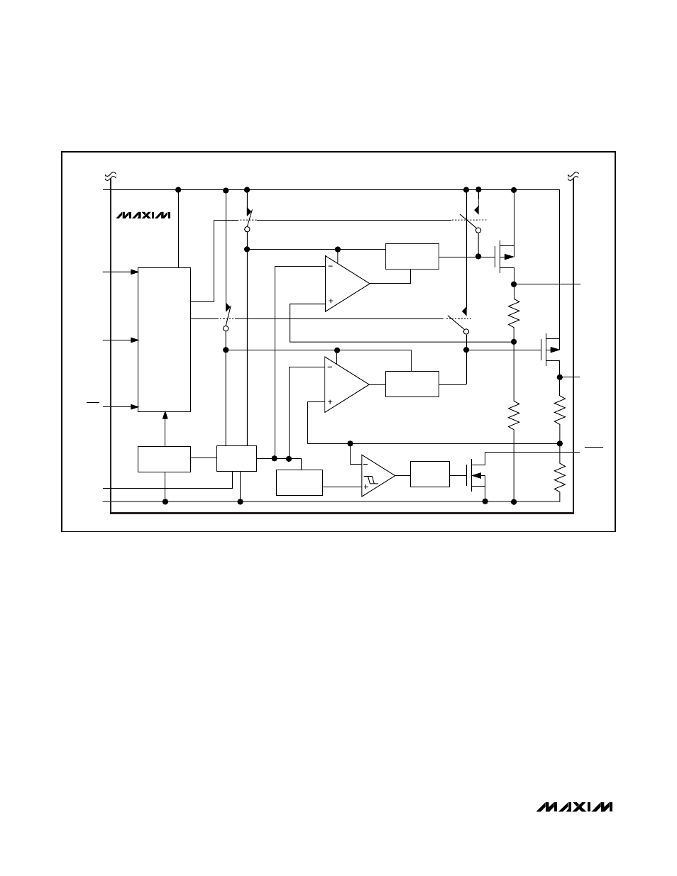
Figure 3. Linear-Regulator Functional Diagram