Rainbow Electronics MAX8620 User Manual
Page 2
MAX8620Y
µPMIC for Microprocessors or DSPs
in Portable Equipment
2
_______________________________________________________________________________________
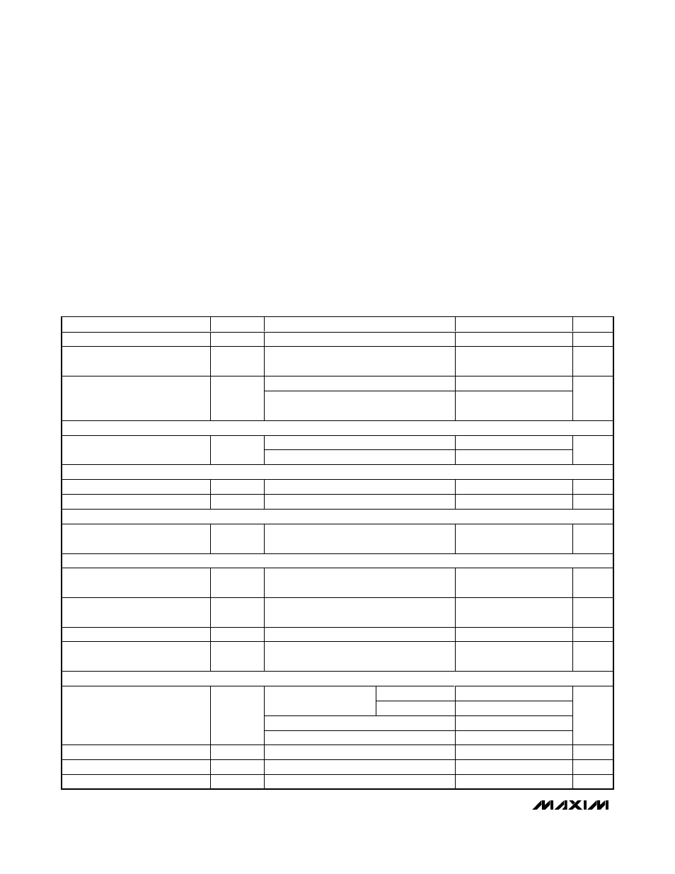
ABSOLUTE MAXIMUM RATINGS
ELECTRICAL CHARACTERISTICS
(V
IN1
= V
IN2
= +3.7V, C
IN
= 10µF, C
BP
= 0.01µF, T
A
= -40°C to +85°C, unless otherwise noted. Typical values are at T
A
= +25°C.)
(Note 1)
Stresses beyond those listed under “Absolute Maximum Ratings” may cause permanent damage to the device. These are stress ratings only, and functional
operation of the device at these or any other conditions beyond those indicated in the operational sections of the specifications is not implied. Exposure to
absolute maximum rating conditions for extended periods may affect device reliability.
IN1, IN2, PWR_ON, RESET, EN2, SEL1, SEL2,
HF_PWR, FB, BP to GND ..................................-0.3V to +6.0V
OUT1, OUT2 to GND .................................-0.3V to (V
IN1
+ 0.3V)
LX Current ......................................................................1.5A
RMS
Continuous Power Dissipation (T
A
= +70°C)
14-Pin TDFN (derate 18.2mW/°C above +70°C) .......1454mW
Operating Temperature Range ...........................-40°C to +85°C
Junction Temperature ......................................................+150°C
Storage Temperature Range .............................-65°C to +150°C
Lead Temperature (soldering, 10s) .................................+300°C
PARAMETER
SYMBOL
CONDITIONS
MIN
TYP
MAX
UNITS
Supply Voltage Range
V
IN1
2.7
5.5
V
Shutdown Supply Current
I
SHDN
V
IN1
= V
IN2
= 4.2V, PWR_ON = HF_PWR =
GND
5.5
10
µA
All outputs enabled, no load
115
140
Supply Current
I
IN1
+ I
IN2
V
OUT1
= V
OUT3
= 1.8V, I
OUT1
= I
OUT3
=
500µA, OUT2 disabled
430
µA
UNDERVOLTAGE LOCKOUT
V
IN1
= V
IN2
rising
2.70
2.85
3.05
UVLO Threshold
V
UVLO
V
IN1
= V
IN2
falling
2.35
V
THERMAL PROTECTION
Thermal-Shutdown Threshold
Temperature rising
+160
°C
Thermal-Shutdown Hysteresis
15
°C
REFERENCE (BP)
Reference Bypass Output
Voltage
V
BP
0
≤ I
BP
≤ 1µA
1.231
1.250
1.269
V
LOGIC AND CONTROL INPUTS (PWR_ON, HF_PWR, EN2)
PWR_ON, HF_PWR, EN2 Input
Low Voltage
V
IL
V
IN1
= V
IN2
= 2.7V to 4.2V (Note 2)
0.4
V
PWR_ON, HF_PWR, EN2 Input
High Voltage
V
IH
V
IN1
= V
IN2
= 2.7V to 4.2V
(Note 2)
1.44
V
Input Bias Current
I
INB
V
PWR_ON
= V
HF_PWR
= V
EN2
= 0V or 5.5V
-1
+1
µA
HF_PWR Timer
t
HF
From the rising edge of HF_PWR until the
one-shot timer expires (Figure 4)
1.05
1.31
1.46
s
LINEAR REGULATORS (OUT1, OUT2)
0°C to +85°C
-1.3
+1.8
I
LOAD
= 1mA, 3.7V
≤ V
IN
≤ 5.5V
-40°C to +85°C
-1.5
+1.8
1mA
≤ I
LOAD
≤ 300mA
-1.2
OUT1, OUT2 Output-Voltage
Accuracy
V
OUT1
,
V
OUT2
I
LOAD
= 150mA
0
%
OUT1, OUT2 Output Current
I
OUT_
300
mA
OUT1, OUT2 Output Current Limit
I
LIM_
V
OUT_
= 0V
310
550
940
mA
OUT1, OUT2 Dropout Voltage
V
DO
I
LOAD
= 200mA, T
A
= +85°C (Note 3)
200
380
mV