Rainbow Electronics MAX8620 User Manual
Page 13
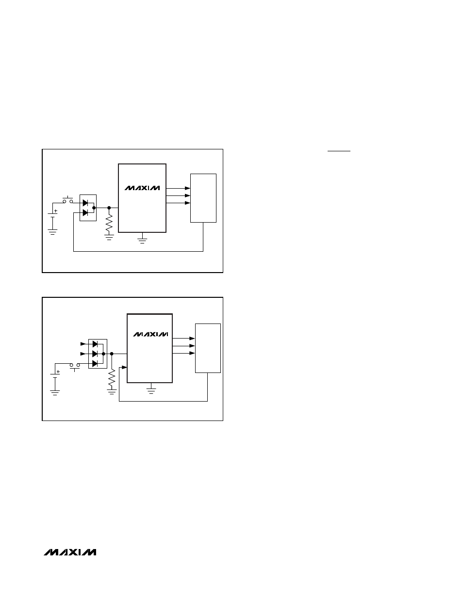
If a long-key press is preferred, see
Figure 6. PWR_ON
must remain high until a microprocessor asserts a logic-
high signal when using this circuit. If a system includes
multiple power-on sources, use a diode OR configura-
tion, as shown in Figure 7.
Setting the Step-Down Output Voltage
(OUT3)
Select a step-down converter output voltage between
0.6V and 3.3V by connecting a resistor voltage-divider
between LX, FB, and GND (see Figure 2). The FB bias
current, I
FB
, is typically 10nA. Select R2 so the resistor-
divider bias current dominates I
FB
by a factor of 10. A
wide range of resistor values is acceptable, but a good
starting point is to choose R2 = 100k
Ω. R1 is given by:
where V
FB
= 0.6V.
V
OUT3
can be set between 0.6V and 3.3V, but the step-
down converter dropout voltage and inductor voltage
drop impact how close V
OUT3
can be to V
IN2
. Total
dropout voltage is a function of the pFET on-resistance,
the DCR of the inductor, and the load as follows:
For example, with 300mA load:
As a result, V
IN1
= V
IN2
must exceed the desired
V
OUT3
by 210mV to maintain regulation.
Inductor Selection
The MAX8620Y step-down converter operates with induc-
tors between 1µH and 4.7µH. Low inductance values are
physically smaller but require faster switching, which
results in some efficiency loss. See the Typical Operating
Characteristics section for efficiency and switching fre-
quency versus inductor value plots. The inductor’s DC
current rating needs to be only 100mA greater than the
application’s maximum load current because the
MAX8620Y step-down converter features zero-current
overshoot during startup and load transients.
For output voltages above 2.0V, when light-load effi-
ciency is important, the minimum recommended induc-
tor is 2.2µH. For optimum voltage-positioning load
transients, choose an inductor with DC series resis-
tance in the 50m
Ω to 150mΩ range (Table 3). For high-
er efficiency at heavy loads (above 200mA) or minimal
load regulation (but some transient overshoot), the
resistance should be kept below 100m
Ω. For light-load
applications up to 200mA, much higher resistance is
acceptable with very little impact on performance.
V
mA
m
mV
OUT DO
3
300
0 65
50
210
(
)
.
=
×
+
(
)
=
Ω
Ω
V
I
R
DCR
OUT DO
OUT
ONP
INDUCTOR
3
3
(
)
=
×
+
(
)
R
R
V
V
OUT
FB
1
2
1
3
=
⎛
⎝⎜
⎞
⎠⎟
−
MAX8620Y
µPMIC for Microprocessors or DSPs
in Portable Equipment
______________________________________________________________________________________
13
µP
POWER-ON
KEY
POWER-HOLD SIGNAL
PWR_ON
V
CORE
V
I/O
V
ANA
1M
Ω
PWR HOLD
MAX8620Y
Figure 6. Long-Key Power-On Closed Loop
µP
POWER-ON
KEY
POWER-HOLD SIGNAL
HF_PWR
PWR_ON
V
CORE
V
I/O
V
ANA
1M
Ω
PWR HOLD
MAX8620Y
AC ADAPTER
HANDS-FREE KIT
Figure 7. Multiple Power-On Inputs